Chemical fusion of non-metallic pipe joints

a non-metallic pipe and chemical fusion technology, applied in the direction of hose connection, coupling, other domestic objects, etc., can solve the problem of difficult joining of non-metallic pipes with adhesives, and achieve the effect of reducing shear stress

Active Publication Date: 2008-03-11
IPS WELD ON DIV
View PDF24 Cites 42 Cited by
  • Summary
  • Abstract
  • Description
  • Claims
  • Application Information

AI Technical Summary

Benefits of technology

[0020]With aligned annular channels filled with adhesive, the adhesive forms an in situ key, therein producing an adhesive joint that is a combination of a mechanical and an adhesive joint. The mechanistic combination reduces the shear stress between the adhesive and the pipe, and assures that even under conditions where there is shear failure, that the pipes will still remain joined, and the joint will continue to function. The annular channels also create an avenue for the extruded adhesive to distribute evenly around the circumference of the pipe end, and then flow toward longitudinally filling the gap. The channels serve to express entrained air and act as a reservoir, which can supply the adhesive over a much longer route than would be available if channeled through the inlet port directly into the gap.

Problems solved by technology

As discussed in the Background, joining non-metallic pipes with an adhesive is especially difficult for olefinic pipes, as these pipes are comprised of low surface energy polymers that are substantially impervious to solvents.

Method used


Image

  • Chemical fusion of non-metallic pipe joints
  • Chemical fusion of non-metallic pipe joints
  • Chemical fusion of non-metallic pipe joints

Examples


Embodiment Construction

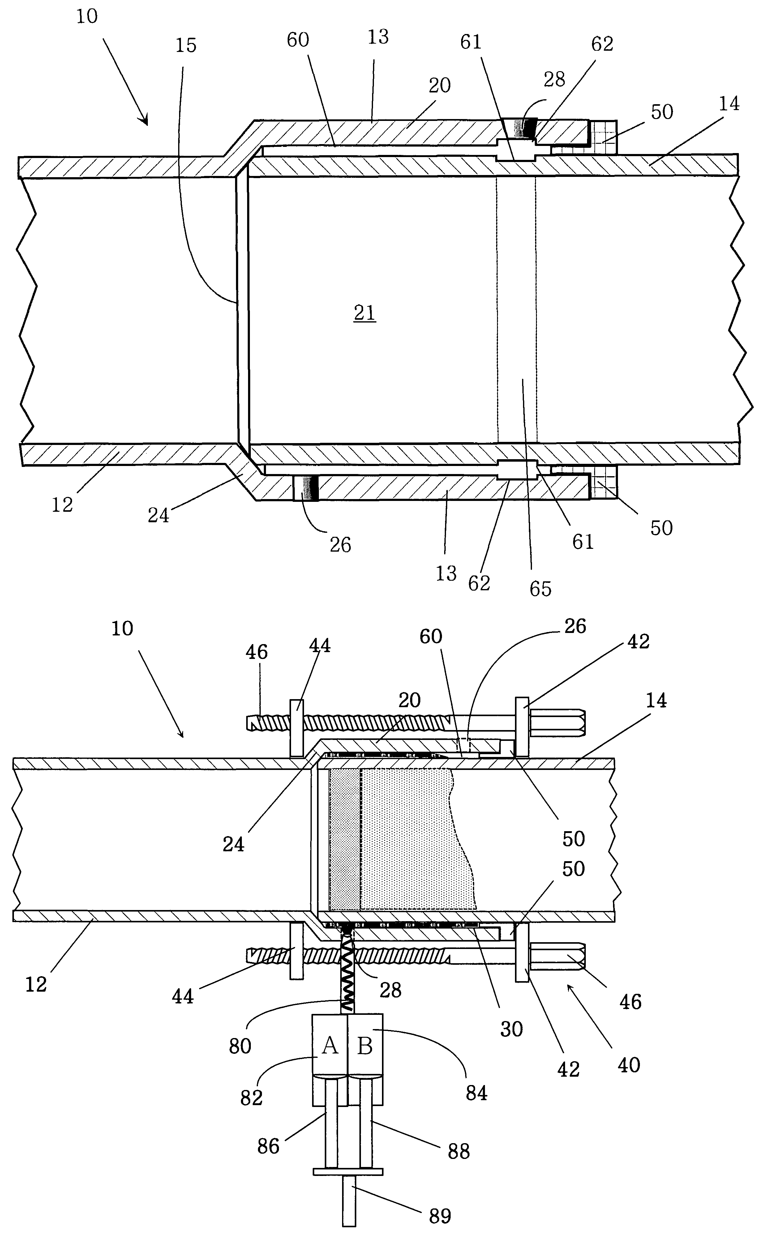
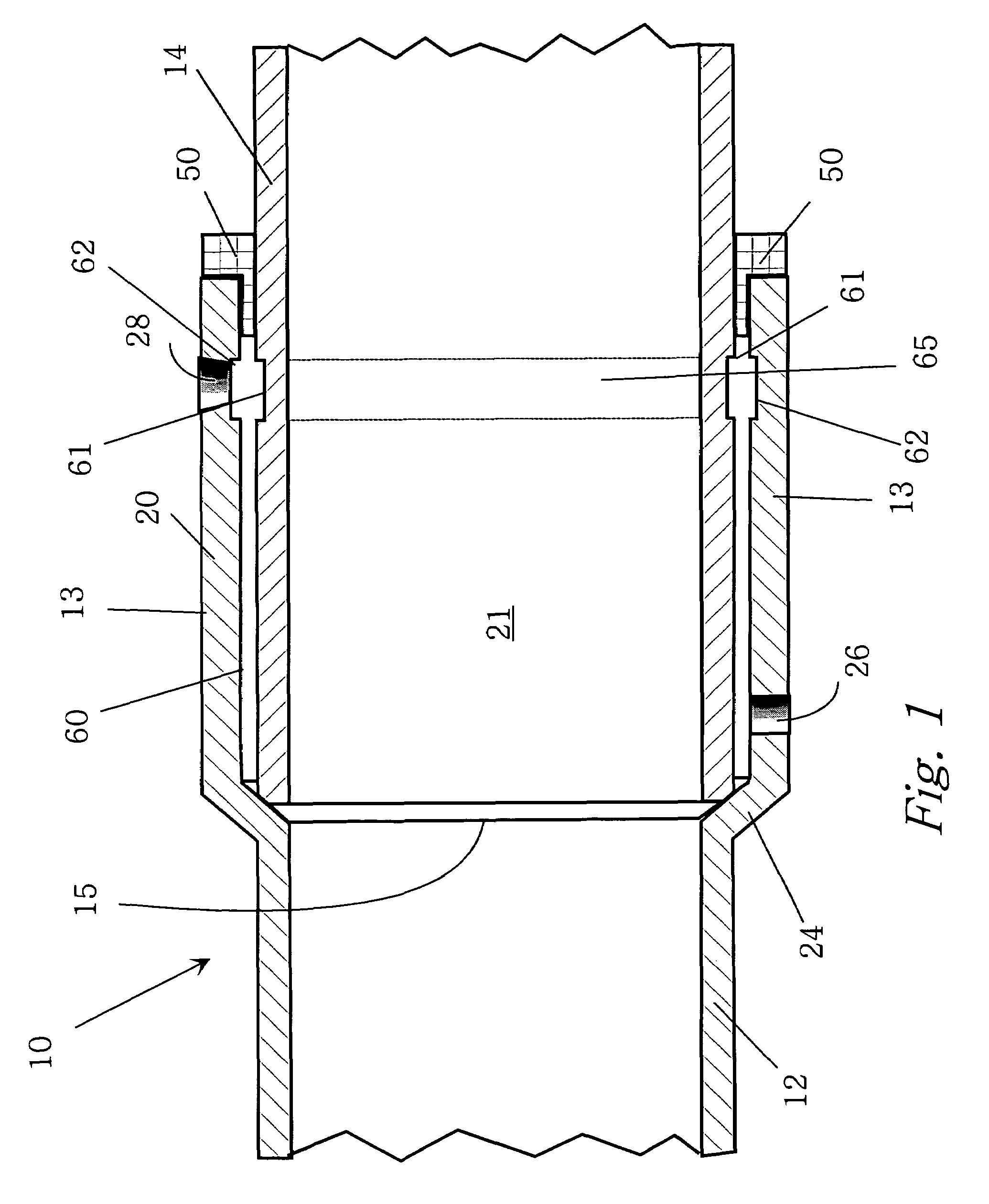
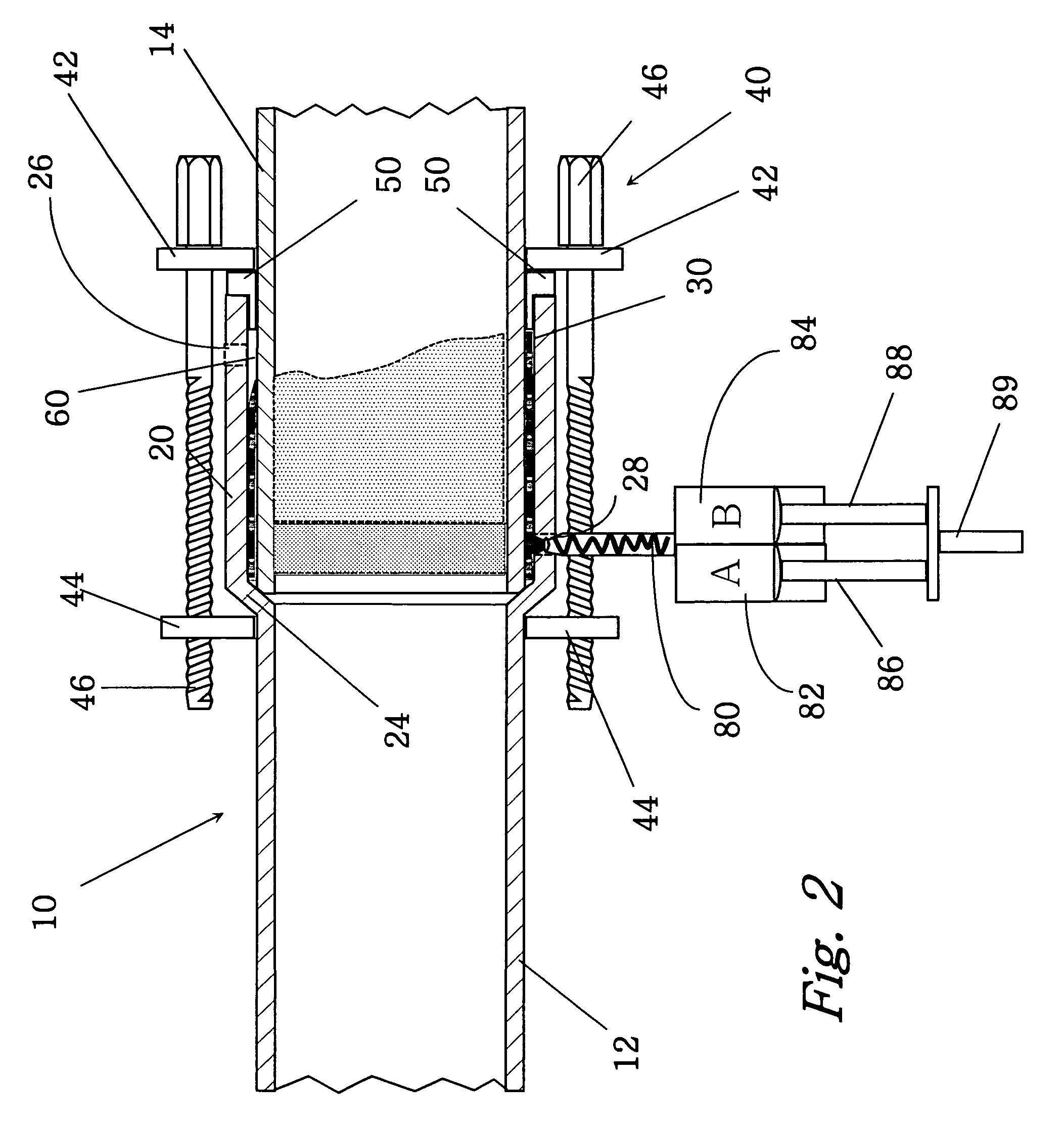
[0030]The invention, as illustrated in the drawings is a pipe joint 10. Referring to FIG. 1, the joint 10 has a first pipe 12 having a socket 20 with an inside diameter, where the socket 20 has a mouth 19 (as shown in FIG. 5), a self-centering bottom 25, and a substantially cylindrical wall 13 with an inlet 28, an outlet 26, and an inner annular channel 62 (also shown in ghost in FIG. 3); a second pipe 14 with an insertion section 21 having a squared-off end 15 and an outer annular channel 61, where said second pipe has an outside diameter that is less than the inside diameter of the socket 20, where the difference in diameters defines a gap 60 and where the outer annular channel 61 aligns with the inner annular channel 62 therein forming an interlocking keyway 65. The inner annular channel 62 and the outer annular channel 61 are substantially deformations in the wall of the socket or the insertion section, respectfully, where a portion of the wall is cutaway or molded into the piec...


PUM

PropertyMeasurementUnit
angleaaaaaaaaaa
surface energyaaaaaaaaaa

Abstract

A pipe joint for joining pipes having a low surface energy and resistance to solvents. The components are an extrudable adhesive; a first pipe having a socket with an inside diameter, where the socket has a mouth, a self-centering bottom, and a cylindrical wall with an inlet, an outlet, and an inner annular channel; a second pipe having an insertion section with an end and an outer annular channel, where the second pipe has an outside diameter that is less than the inside diameter of the socket, the difference in diameters defining a gap and an interlocking keyway; and a flanged annular ring. The annular ring has an inside diameter that enables it to be slid over the second pipe and a thickness that is comparable to the gap. When the adhesive cures it forms a mechanical key. The adhesive is preferably an alkyl borane adhesive.

Description

CROSS REFERENCE TO RELATED PATENT APPLICATION[0001]The application claims the benefit of the priority filing date of the provisional patent application, Ser. No. 60 / 555,923, filed on Mar. 24, 2004.BACKGROUND OF THE INVENTION[0002]1. Field of the Invention[0003]The invention relates generally to a method for joining pipes, and more particularly to a method and a system for joining pipes comprised of low surface energy materials, such as HDPE (high density polyethylene), PEX (cross linked polyethylene), and PVDF (polyvinylidene difluoride). Low energy surface materials are generally to be referred to as olefinic materials within the scope of the disclosure and claims of this application.[0004]2. Prior Art[0005]A process called chemical fusion (employing an adhesive) is used to join olefinic plastic pipes comprised of low surface energy materials, such as HDPE (high density polyethylene), PEX (cross linked polyethylene), and PVDF (polyvinylidene difluoride). Olefinic plastic pipes such...

Claims


Application Information

Patent Timeline
Patent Type & Authority Patents(United States)
IPC IPC(8): F16L13/00F16L13/02F16L13/11F16L47/02
CPCB29C66/342F16L13/116F16L47/02B29C65/542B29C66/52292B29C66/1122B29D23/003B29C66/1222B29C66/1226B29C66/324B29C65/7826B29C66/5221Y10T156/1744B29K2023/06B29K2023/065B29K2023/0691B29K2027/16B29C65/4815B29C65/483B29C65/485B29C65/484B29C66/71B29L2031/7172B29K2083/00B29K2055/02B29K2033/08B29K2031/04B29K2027/18B29K2027/08B29K2027/06B29K2023/16B29K2023/12
Inventor MCPHERSON, TERRY R.
Owner IPS WELD ON DIV
Why Eureka
Try Eureka