Motor structure

a motor and structure technology, applied in the direction of bearings, shafts and bearings, dynamo-electric machines, etc., can solve the problems of high defective rate during assembling, increase production cost and complexity of assembling process, and failure to normally assembled motor structures, so as to reduce parts and assembling processes, and save production costs

Active Publication Date: 2008-03-11
SUNONWEALTH ELECTRIC MACHINE IND
View PDF3 Cites 18 Cited by
  • Summary
  • Abstract
  • Description
  • Claims
  • Application Information

AI Technical Summary

Benefits of technology

[0009]As the limit member of the present invention has an annular wall having a certain height and a center through hole, a plurality of limit protrusions on the inner wall of the through hole are extended toward a center of the through hole for snapping the reduced neck of the spindle...

Problems solved by technology

high production cost and complex assembling processes: In addition to the bearing and the positioning ring, the abrasive gasket, the washer and the retainer ring that are disposed inside the shaft tube of the conventional motor structure result in the production cost hike and complexity of the assembling process, thus coercing assembler to place the above-mentioned parts inside the s...

Method used


Image

  • Motor structure
  • Motor structure
  • Motor structure

Examples


Embodiment Construction

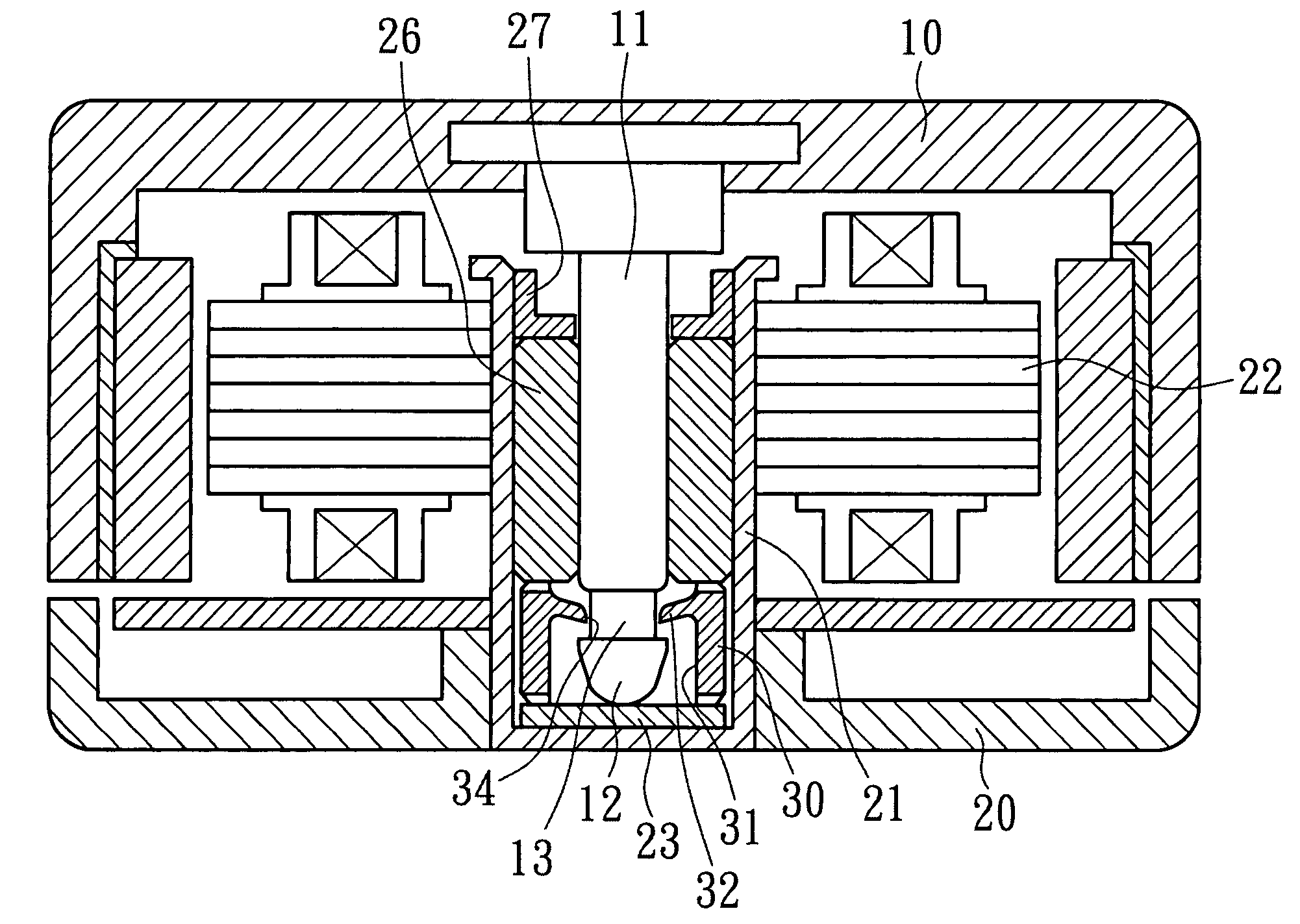
[0015]The present invention relates to a motor structure as shown in FIG. 3, which includes a rotor 10 centrally fixed with one end of a spindle 11, in which an end section 12 is formed on the other end of the spindle 11, and the end section 12 has a reduced neck 13 with a smaller outer diameter; a base having a shaft tube 21 and a stator set 22 disposed thereon, in which the shaft tube 21 is in form of a circular tube, the bottom side thereof shall be in an integrally-formed and closed pattern so as to have a ␣-like cross section, the shaft tube 21 can be assembled or integrally formed on the base 20, an abrasive gasket 23, a limit member 30 and a bearing 26 are sequentially placed in the shaft tube 21, a positioning ring 27 is tightly fitted in the top end opening inside the shaft tube 21 so that the bearing 26, the limit member 30 and so forth are steadily positioned inside the shaft tube 21, the bearing 26 can be any type of a sleeve bearing, a roller bearing, a hydrodynamic bea...


PUM


Abstract

The present invention relates to a motor structure, which has a shaft tube and a stator set disposed on a base. The shaft tube is in form of a circular tube, the bottom side thereof is in an integrally-formed and closed pattern, and an abrasive gasket, a limit member and a bearing are disposed in the shaft tube, such that a spindle of a rotor can be inserted in the bearing and rotate therein. As the limit member has an annular wall with a specific height, a plurality of limit protrusions extended inward from the inner wall of the through hole can snap a reduced neck of the spindle to limit its axial displacement, thereby attaining the design object of reserving enough space for accommodating an end section of the spindle, reducing necessary parts, assembling process, and saving production cost.

Description

FIELD OF THE INVENTION[0001]The present invention relates to a motor structure, and more particularly to a practical structure that can save cost, labor hour and production process and secure fast and convenient assembly.BACKGROUND OF THE INVENTION[0002]As shown in FIG. 1, a conventional motor structure includes a rotor 10 centrally bundled and fixed with one end of a spindle, in which a end section 12 is formed on the other end of the spindle 11, and a reduced neck 13 with a smaller outer diameter is formed over the end section 12; a base 20 having a shaft tube 21 and a stator set 22 disposed thereon, in which the shaft tube 21 can be assembled or integrally formed on the base, the bottom end of the shaft tube 21 is sealed, an abrasive gasket 23, a washer 24, a retainer ring 25 and a bearing 25 are sequentially placed in the shaft tube 21, a positioning ring 27 is tightly fixed inside the shaft tube 21 near an opening at one end thereof so as to steadily position the bearing 26, th...

Claims


Application Information

Patent Timeline
IPC IPC(8): H02K15/00
CPCH02K5/1675H02K7/085H02K2205/03Y10S384/903
Inventor HORNG, ALEXSAN, TO-NIEN
Owner SUNONWEALTH ELECTRIC MACHINE IND
Why Eureka
Try Eureka