
Phosphor mixture and light emitting device using the same

a technology of phosphor mixture and light emitting device, which is applied in the direction of discharge tube luminescnet screen, silicon compound, sustainable building, etc., can solve the problems of extremely weak green and red which are required for a light source for illumination, unfavorable color rendering of this light source, and emitting a slightly bluish white light. achieve excellent color rendering

Active Publication Date: 2008-03-18
NICHIA CORP +1
View PDF90 Cites 55 Cited by
  • Summary
  • Abstract
  • Description
  • Claims
  • Application Information

AI Technical Summary

Problems solved by technology

However, since this type is composed of blue emitting light and yellow emitting light, it presents a problem that green and red which are required for a light source for illumination is extremely weak.
Especially, a color component for a long-wavelength side or red in the visible light region is insufficient, which results in emitting a slightly bluish white light though it is still in white zone so far.
Accordingly, when this white LED is used for a general-purpose illumination, a red object appears to be very dull red, which means color rendering of this light source is very unfavorable.
Furthermore, as it has no red light-emission component, it is impossible to obtain reddish white emitting-light like warm white at a correlated color temperature of 4000 K or less.
However, in white LED illumination by combination of a near-ultraviolet / ultraviolet LED and a phosphor in RGB or others, there is a problem that a red phosphor among RGB phosphors is especially low in emission efficiency compared with phosphors in other colors.
Accordingly, when manufacturing a white LED, mixing ratio of the red phosphor is required to be extremely high compared with phosphors in other colors among the mixing ratio of the phosphors, which results in reduction of mixing ratios of the phosphors in other colors, so that a white color in high luminance cannot be obtained.
Especially, as for a white LED requiring a light having a low color temperature such as warm white in which a mixing ratio of a long wavelength side (red color side) component is high, a necessary amount of a red phosphor is further increased, which causes a more pronounced problem that emission with high luminance as a whole cannot be obtained Therefore, in recent years, in order to solve the problem that exciting efficiency on a long wavelength side of the red phosphor described above is low compared with phosphors in other colors, a phosphor containing nitrogen such as silicon nitride series or the like is reported as a red phosphor which has a favorable excitation band on the long wavelength side, and can obtain a fluorescence peak having a wide half band width.
However, based on the studies by the present inventors, it becomes clear that a light having favorable color rendering cannot be obtained even by the above-described method in a region of color temperature at 4500 K or less, especially in a reddish warm white of about 3000 K in color temperature, it is found that it is impossible to obtain a light in favorable color rendering.
Besides, it is found that even in a white light by combining a near-ultraviolet / ultraviolet LED with a phosphor in RGB and others, though a white light in a region with a low color temperature can be obtained by using a known red phosphor as a red emission component, a light in favorable color rendering cannot be obtained.
However, it was found that such red phosphors were low in emission efficiency when excited by the light of blue LED or ultraviolet LED and couldn't obtain a light having high color rendering.
However, it was found that it was insufficient to improve the color rendering with a phosphor mixture including a red phosphor of a conventional technology.

Method used


Image

  • Phosphor mixture and light emitting device using the same
  • Phosphor mixture and light emitting device using the same
  • Phosphor mixture and light emitting device using the same

Examples


example 1

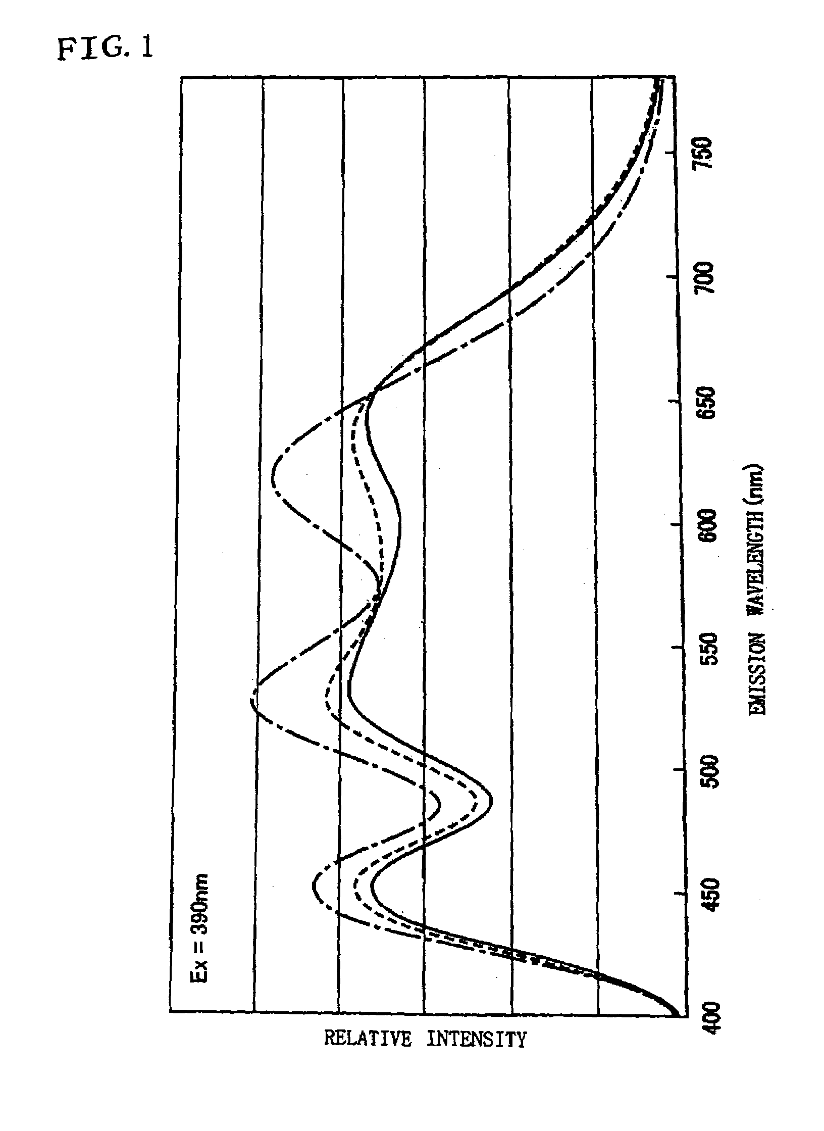
[0129]In example 1, when excited by a light-emitting element (LED) emitting light having an emission spectrum having a peak wavelength at 390 nm, a phosphor mixture producing emission at the correlated color temperature of 5000 K was prepared, and emission characteristics and color rendering of the phosphor mixture was evaluated.

[0130]1) Preparation of Phosphors

[0131]A red phosphor CaAlSiN3:Eu was manufactured by the method explained in the embodiments.

[0132]An orange phosphor CaAl2Si4N8:Eu was manufactured in the same way as the red phosphor CaAlSiN3:Eu, except formulation ratio of raw materials of 0.950 / 3 mol of Ca3N2, 2 mol of AlN, 4 / 3 mol of Si3N4 and 0.050 / 2 mol of Eu2O3.

[0133]For a green phosphor ZnS:Cu,Al and a blue phosphor BAM:Eu, commercially available products were prepared.

[0134]2) Formulation of a Phosphor Mixture

[0135]An emission spectrum created by exciting the above-described four kinds of phosphors which were CaAlSiN3:Eu, CaAl2Si4N8:Eu, ZnS:CuAl and BAM:Eu with exci...

example 2

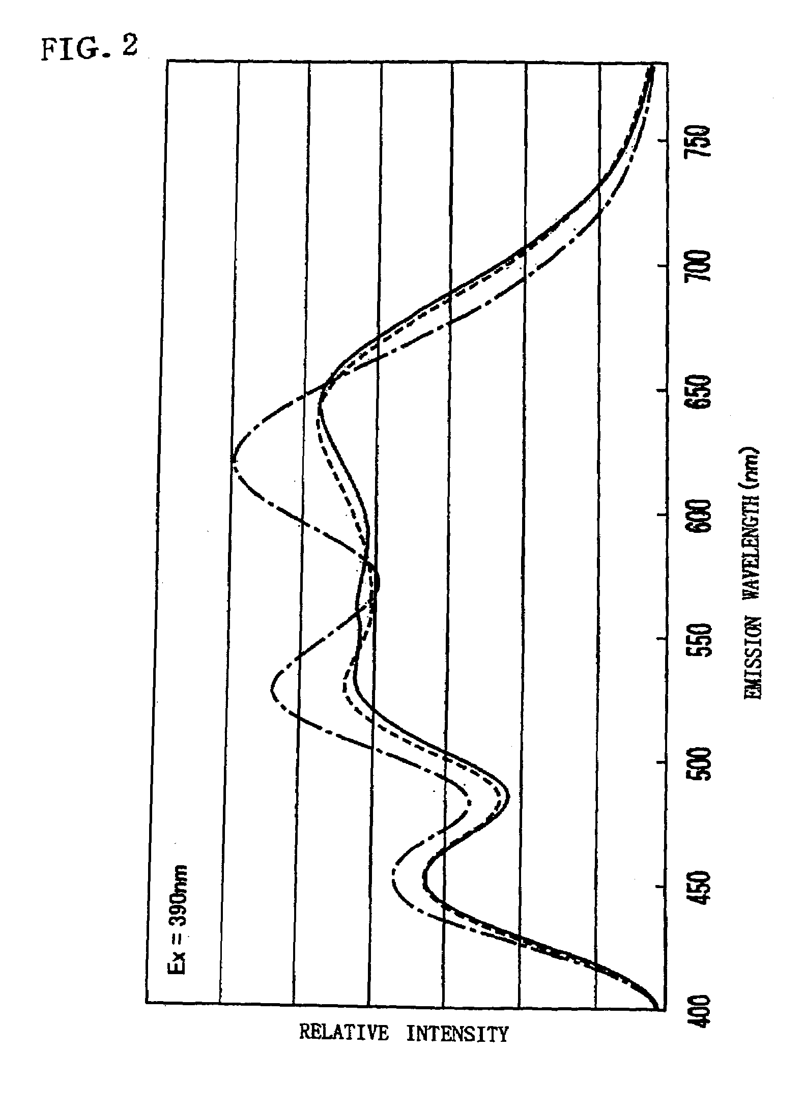
[0146]Also in example 2, a phosphor mixture producing emission at a correlated color temperature of 5000 K was manufactured, and emission characteristics and color rendering of the phosphor mixture were evaluated.

[0147]1). Preparation of Phosphors

[0148]A red phosphor CaAlSiN3:Eu was manufactured by the method explained in the embodiments.

[0149]An orange phosphor 2.75SrO.Si3N4:Eu was manufactured in the same way as the red phosphor CaAlSiN3:Eu, except formulation ratio of raw materials of 2.71 mol of SrCO3, 1 mol of Si3N4, and 0.040 / 2 mol of Eu2O3.

[0150]For a green phosphor ZnS:Cu,Al and a blue phosphor BAM:Eu, commercially available products were prepared.

[0151]2) Formulation of a Phosphor Mixture

[0152]In the same way as in example 1, CaAlSiN3:Eu2.75SrO Si3N4:Eu:ZnS:Cu,Al:BAM:Eu=0.01:0.16:0.38:0.45 was found, and a phosphor mixture was obtained by weighing and mixing the respective phosphors according to the result.

[0153]Here, when being excited by the excitation light having an emi...

example 3

[0161]Also in example 3, a phosphor mixture producing emission at a correlated color temperature of 5000 K was manufactured, and emission characteristics and color rendering of the phosphor mixture were evaluated.

[0162]1). Preparation of Phosphors

[0163]A red phosphor CaAlSiN3:Eu was manufactured by the method explained in the embodiments.

[0164]An orange phosphor Ca2Si5N8:Eu was manufactured in the same way as the red phosphor CaAlSiN3:Eu, except formulation ratio of raw materials of 1.98 / 3 mol of Ca3N2, 5 / 3 mol of Si3N4, and 0.020 / 2 mol of Eu2O3.

[0165]For a green phosphor ZnS:Cu,Al and a blue phosphor BAM:Eu, commercially available products were prepared.

[0166]2) Formulation of a Phosphor Mixture

[0167]In the same way as in example 1, CaAlSiN3:Eu:Ca2Si5N8:EuZnS:Cu,Al:BAM:Eu=0.04:0.17:0.31:0.48 was found, and a phosphor mixture was obtained by weighing and mixing the respective phosphors according to the result.

[0168]Here, when being excited by the excitation light having an emission ...


PUM

PropertyMeasurementUnit
wavelength rangeaaaaaaaaaa

Abstract

A phosphor mixture containing four or more kinds of phosphors including a red phosphor, an orange phosphor, a blue phosphor, and a green phosphor, to produce emission having excellent color rendering of white light at a high color temperature, and emission in warm white which is low in color temperature, and a light emitting device including the phosphor mixture and a light-emitting section, CaAlSiN3:Eu and CaAl2Si4N8:Eu are manufactured as a red phosphor and an orange phosphor respectively, and ZnS:Cu, Al, and BAM:Eu are prepared as a green phosphor and a blue phosphor respectively. The emission spectrums of these phosphors are measured and a relative mixing ratio at which the correlated color temperature of the phosphor mixture becomes a targeted color temperature is determined from the emission spectrum by simulation, and a phosphor mixture is obtained by weighing and mixing the respective phosphors based on the simulation result.

Description

BACKGROUND OF THE INVENTION[0001]1. Field of the Invention[0002]The present invention relates to a phosphor mixture used for an illumination device and the like such as a light-emitting diode (LED), a vacuum fluorescent display, a fluorescent lamp, and the like, and an light emitting device using the phosphor mixture.[0003]2. Description of the Relevant Art[0004]As a light emitting device which has been conventionally used for an illumination device, a discharge-type fluorescent lamp, an incandescent lamp and the like can be cited. However, a light-emitting diode emitting a white light has been recently developed. The white LED illumination is an ideal illumination device having such merits of lower heat generation, better luminous efficacy, and lower power consumption compared to a conventional light source for illumination, and a long life without burnt-out of a filament like a conventional incandescent lamp because it is formed of only a semiconductor or a semiconductor and phosp...

Claims


Application Information

Patent Timeline
Patent Type & Authority Patents(United States)
IPC IPC(8): H01J1/62H01J63/04H01L33/50H01L33/56H01L33/62
CPCC04B35/581C04B35/584C09K11/642C09K11/7734H01L33/504C04B2235/3213C04B2235/3224C04B2235/3852C04B2235/3865C04B2235/3873Y02B20/181H01L33/505H01L33/507H01L2224/48091H01L2224/48247H01L2224/48257H01L2924/00014Y02B20/00C09K11/77348
Inventor NAGATOMI, AKIRAGOTOH, MASAHIROSAKANE, KENJI
Owner NICHIA CORP
Learn More