Rotation-type working machine
a working machine and rotating technology, applied in the direction of dynamo-electric machines, position/direction control, stopper details, etc., can solve the problems of decreased operation efficiency and known arts, and achieve the effects of reducing excavation reaction force, preventing damage to parking brakes or the like due to rotating external force, and reducing working efficiency
- Summary
- Abstract
- Description
- Claims
- Application Information
AI Technical Summary
Benefits of technology
Problems solved by technology
Method used
Image
Examples
first embodiment (see figs.1 to 3)
First Embodiment (see FIGS. 1 to 3)
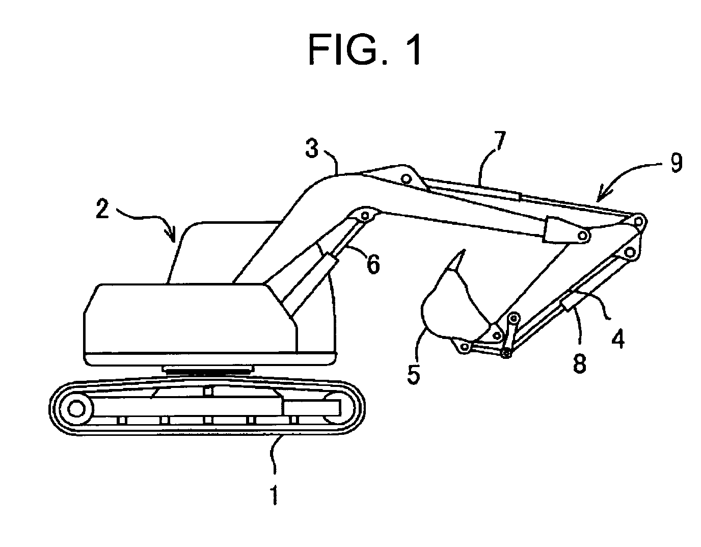
[0036]FIG. 1 illustrates a shovel to which the present invention is applied.
[0037]In the shovel, an upper rotating body 2 is rotatable around a vertical axis and mounted on a crawler type lower traveling body 1. On the upper rotating body 2, a working (excavation) device 9 which has a boom 3, an arm 4, a bucket 5, and cylinders (hydraulic cylinder) 6, 7, and 8 of each of the boom, the arm, and the bucket which drive them, is mounted.
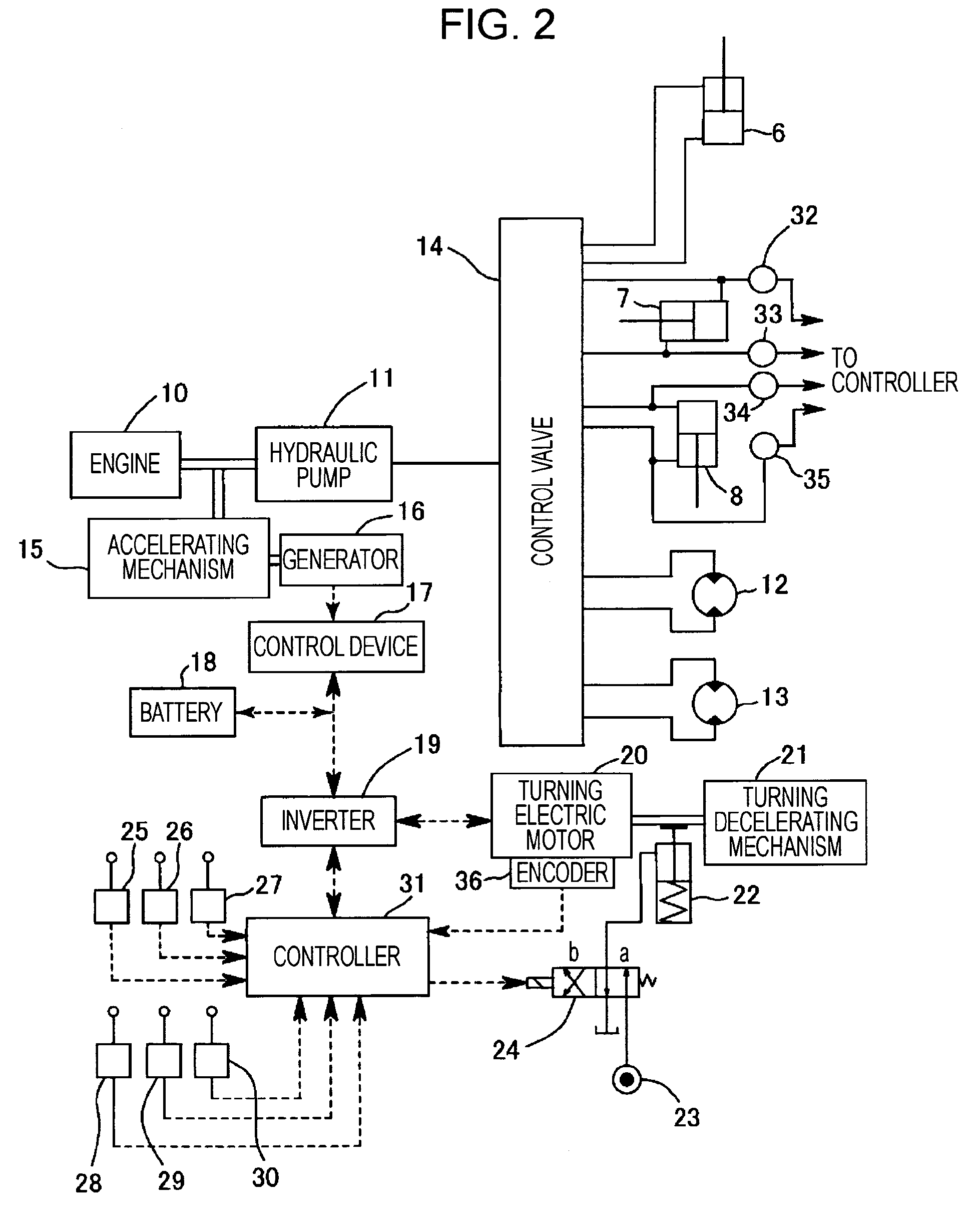
[0038]FIG. 2 illustrates a block diagram of an overall driving system and an overall control system of the shovel.
[0039]As shown in the drawing, a hydraulic pump 11 is driven by an engine 10 and the discharged oil is supplied to the cylinders 6, 7, and 8 of each of the boom, the arm, and the bucket and right and left traveling motors 12 and 13 which drive the lower traveling body 1 through a control valve 14 (although the valve is provided to each actuator, in this case, it is shown as a valve block).
[0040]Further, to t...
second embodiment (see figs.4 and 5)
Second Embodiment (see FIGS. 4 and 5)
[0066]In each embodiment below, only deference from the first embodiment is described.
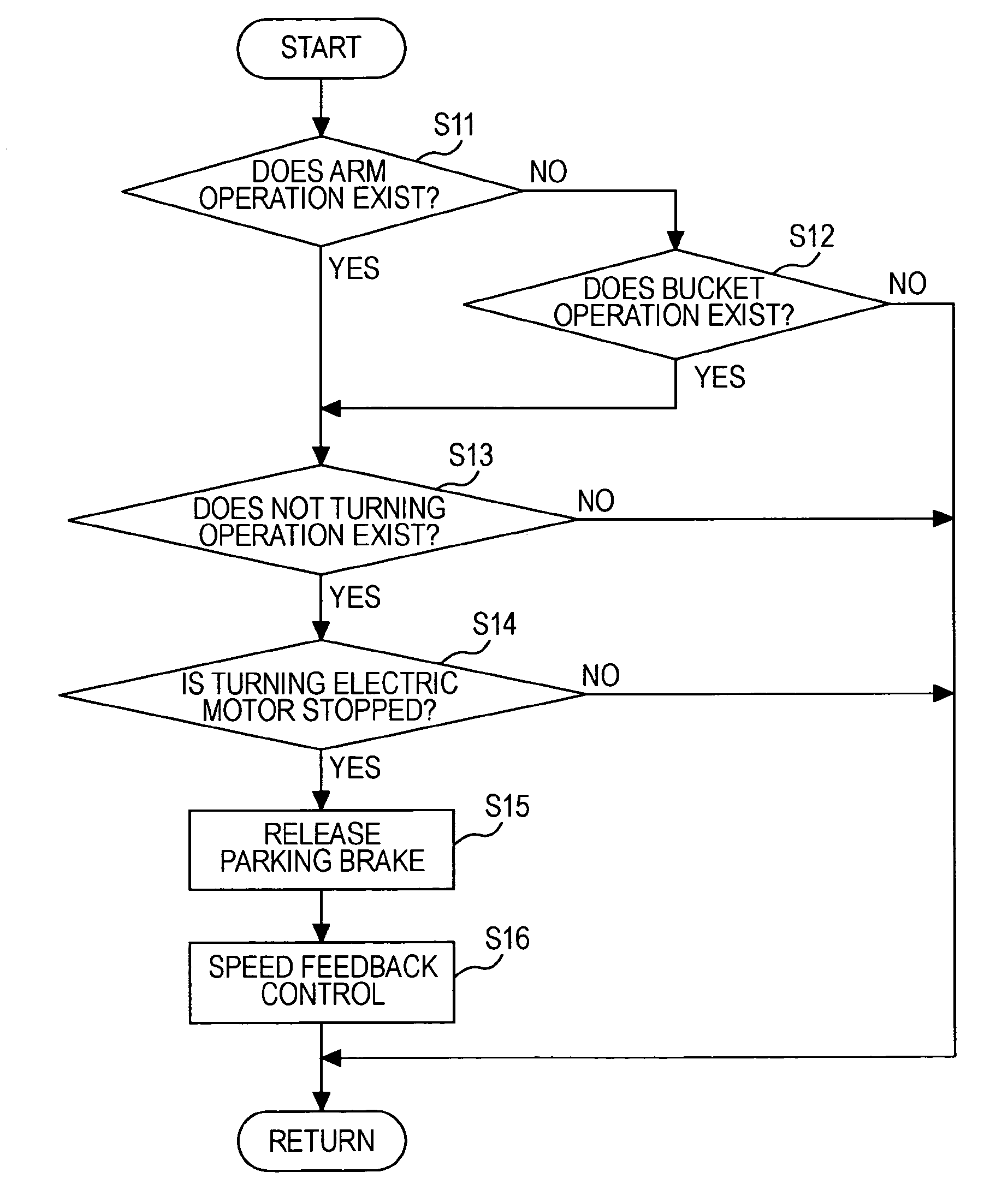
[0067]In the first embodiment, the main purpose is to protect the parking brake 22 and the rotating driving part when at least one of the arm operation and the bucket operation is carried out by carrying out only the release of the parking brake 22. On the other hand, in the second and other embodiments, while releasing the parking brake 22, the rotating electric motor 20 is controlled in a direction holding the upper rotating body 2 in a stopped state.
[0068]Further, in each of the second to fifth embodiments, since the configurations of the hardware themselves are similar to those in the first embodiment and only control contents differ, the configuration of the hardware shown in FIG. 2 is used and only the control contents are described.
[0069]In the second embodiment, as shown in FIG. 4, whether an arm operation exists or not is determined at step S11 and whet...
third embodiment (see fig.6)
Third Embodiment (see FIG. 6)
[0080]In a third embodiment, in place of the speed feedback control described in the second embodiment, a position feedback control is employed.
[0081]That is, steps S21 to 24 are similar to those in the steps S11 to S14 in FIG. 4, at step S25, a rotating position of the time is stored and at step S26, the parking brake 22 is released. Then, at step S27, the position feedback control, that is, based on a position signal from the encoder 36, by a deviation of a position at the time of control start and a position detected later, the feedback control is carried out.
[0082]In this control method, even if the rotating electric motor 20 moves due to external force if the external force is larger than electric motor torque, if the external force becomes smaller than the electric motor torque, the rotating electric motor 20 is controlled to return to a target position.
[0083]According to the position feedback control, as well as the second embodiment, when excavat...
PUM
 Abstract
Description
Claims
Application Information
 - R&D
- Intellectual Property
- Life Sciences
- Materials
- Tech Scout
- Unparalleled Data Quality
- Higher Quality Content
- 60% Fewer Hallucinations
Browse by: Latest US Patents, China's latest patents, Technical Efficacy Thesaurus, Application Domain, Technology Topic, Popular Technical Reports.
© 2025 PatSnap. All rights reserved.Legal|Privacy policy|Modern Slavery Act Transparency Statement|Sitemap|About US| Contact US: help@patsnap.com


