Photonic buoy

a technology of photon buoys and buoys, applied in special-purpose vessels, television systems, instruments, etc., can solve the problems of putting both submarines and surface craft at risk, sonar and the submarine's periscope not always avoiding submarine/surface craft, and the primary risk of the submarine coming to periscope depth in a littoral environmen

Inactive Publication Date: 2008-03-18
RAYTHEON CO
View PDF15 Cites 23 Cited by
  • Summary
  • Abstract
  • Description
  • Claims
  • Application Information

AI Technical Summary

Benefits of technology

[0011]It is a further object of this invention to provide such a photonic buoy system which provides a stable composite image of the horizon.
[0012]It is a further object of this invention to provide a photonic buoy system with a very long transmission cable tether to allow the submarine to maneuver freely even when the photonic buoy is deployed.

Problems solved by technology

The transition of a submarine from deep under the ocean surface to periscope depth can place both the submarine and surface craft at risk.
As evident by the incidents involving the U.S.S. Greenville and the U.S.S. Jacksonville submarines, the present procedures using passive sonar and the submarine's periscope do not always avoid submarine / surface craft collisions.
The primary risk to the submarine coming to periscope depth in a littoral environment is a quiet surface contact such as a fishing vessel or pleasure craft.
This attempt was unsuccessful, however, because of the very low height-of-eye of the buoy due to the weight of the mechanical image stabilization subsystem and the limitation of the package to the dimensions of an unmodified three inch launcher.
Also, the very short copper wire tether used to transmit the video signal prevented full deployment of this system.
This system, however, does not work when the depth of the submarine is beyond a certain limit, when the water is murky, when it is cloudy or dark, or when large waves are present on the ocean's surface.

Method used


Image

  • Photonic buoy
  • Photonic buoy
  • Photonic buoy

Examples


Embodiment Construction

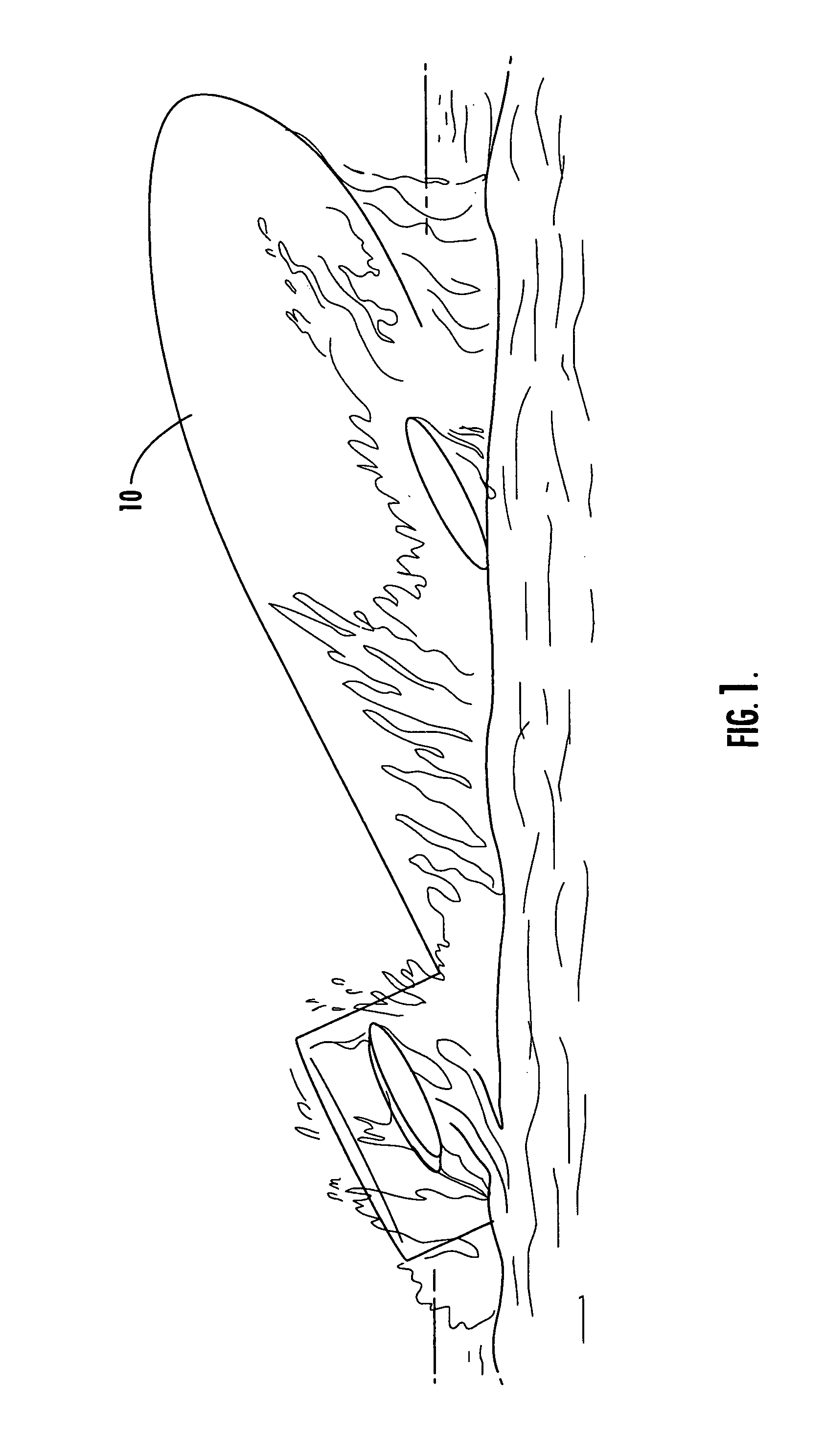
[0029]As shown in FIG. 1, when submarine 10 surfaces, it can a be fairly violent event subjecting submarine 10 and any surface craft proximate submarine 10 to damage or, worse, injury or death to the occupants of submarine 10 and / or the surface craft.

[0030]In the Background section above, the prior art attempts to prevent such collisions and / or to prevent detection of submarine 10 have largely failed.

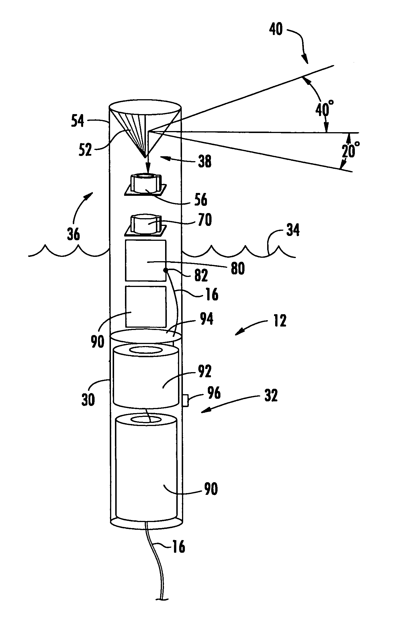
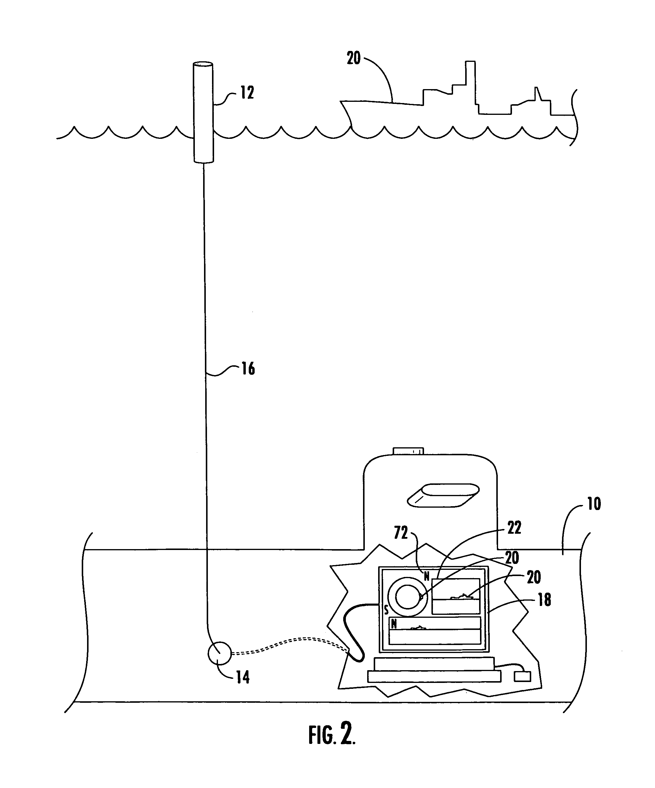
[0031]In this invention, long before submarine 10, FIG. 2 reaches periscope depth, 4-6′ long buoy 12 is deployed from launcher 14 of submarine 10, typically a three inch counter measure launcher usually used to launch flares and expendable Bathythermographs (XBTs). Submarine 10 may be an attack class or Trident class submarine. Buoy 12 is tethered to submarine 10 via cable 16 discussed infra which extends through the breech door of the launcher and interconnects buoy 12 with workstation 18 on board submarine 10.

[0032]Deployment of expendable photonic buoy 12 begins with the loading of t...


PUM


Abstract

A photonic buoy including a lengthy hull with a ballast portion which resides below the waterline and a top portion which is disposed above the waterline; an optical bench at the top portion of the hull configured to provide a panoramic view of the horizon; and a transmission cable extending from the optical bench for transmitting video signals to a remote location.

Description

FIELD OF THE INVENTION[0001]This invention relates to a system for detecting or monitoring the presence of objects on the water to, for example, ensure that a submarine does not collide with surface craft and / or is not detected by hostile forces when the submarine surfaces.BACKGROUND OF THE INVENTION[0002]The transition of a submarine from deep under the ocean surface to periscope depth can place both the submarine and surface craft at risk. As evident by the incidents involving the U.S.S. Greenville and the U.S.S. Jacksonville submarines, the present procedures using passive sonar and the submarine's periscope do not always avoid submarine / surface craft collisions.[0003]The existing practice on board U.S. submarines preparing to surface is to check for existing contacts using passive sonar. If any contacts are determined to be near the submarine and present a possibility of counter-detection or collision, no excursion is made to periscope depth. If no contacts present a risk, the s...

Claims


Application Information

Patent Timeline
Patent Type & Authority Patents(United States)
IPC IPC(8): H04N5/232B63B22/00H04N7/18
CPCH04N7/183B63G8/38H04N23/00
Inventor CROASDALE, WILLIAM
Owner RAYTHEON CO
Why Eureka
Try Eureka