
Vehicle provided with key cylinder device equipped with handle lock mechanism

a key cylinder and handle technology, which is applied in the direction of mechanical control devices, keyhole guards, instruments, etc., can solve the problems of difficult to loosen the bolts from the outside, the bolts are not exposed, and the bolts cannot be easily loosened, so as to improve the assemblyability of the key cylinder device to the vehicle body fram

Inactive Publication Date: 2008-03-25
HONDA MOTOR CO LTD
View PDF17 Cites 25 Cited by
  • Summary
  • Abstract
  • Description
  • Claims
  • Application Information

AI Technical Summary

Benefits of technology

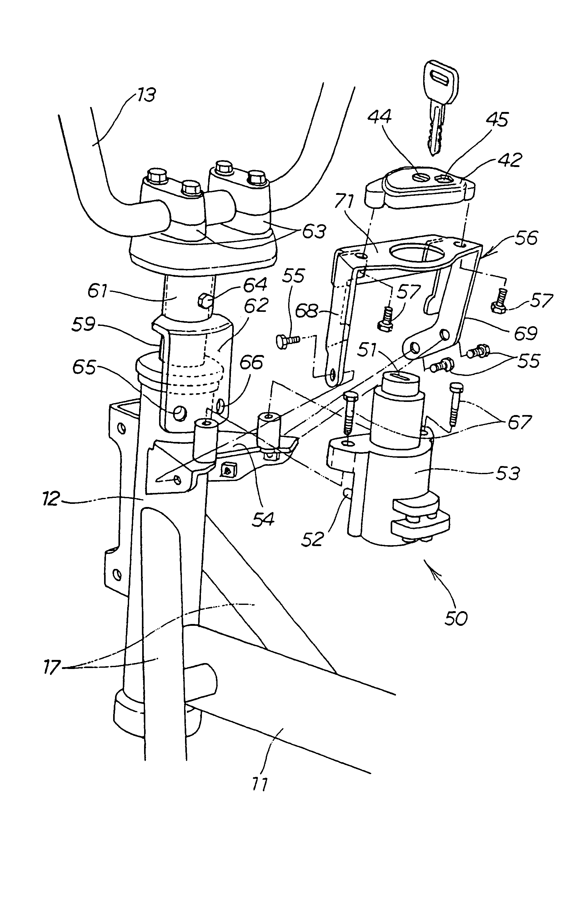
The present invention provides a key cylinder device with a handle lock mechanism that can be easily assembled to a vehicle body frame. The device includes a steering handle, a key cylinder unit, and a bracket for mounting the key cylinder unit to the vehicle body frame. A shutter housing is used to cover the key hole of the key cylinder unit, and the bracket is attached to the key cylinder unit with bolts that are difficult to loosen. The bracket is designed to protect the key cylinder unit from tampering, and the legs on the bracket prevent the possibility of a rod-shaped object reaching the mounting member. The key cylinder unit is mounted to the vehicle body with the mounting member, such as a bolt, and the legs cover the side surface of the mounting member to further prevent the possibility of tampering. The invention improves the assembleability of the key cylinder device to the vehicle body frame and ensures its security.

Problems solved by technology

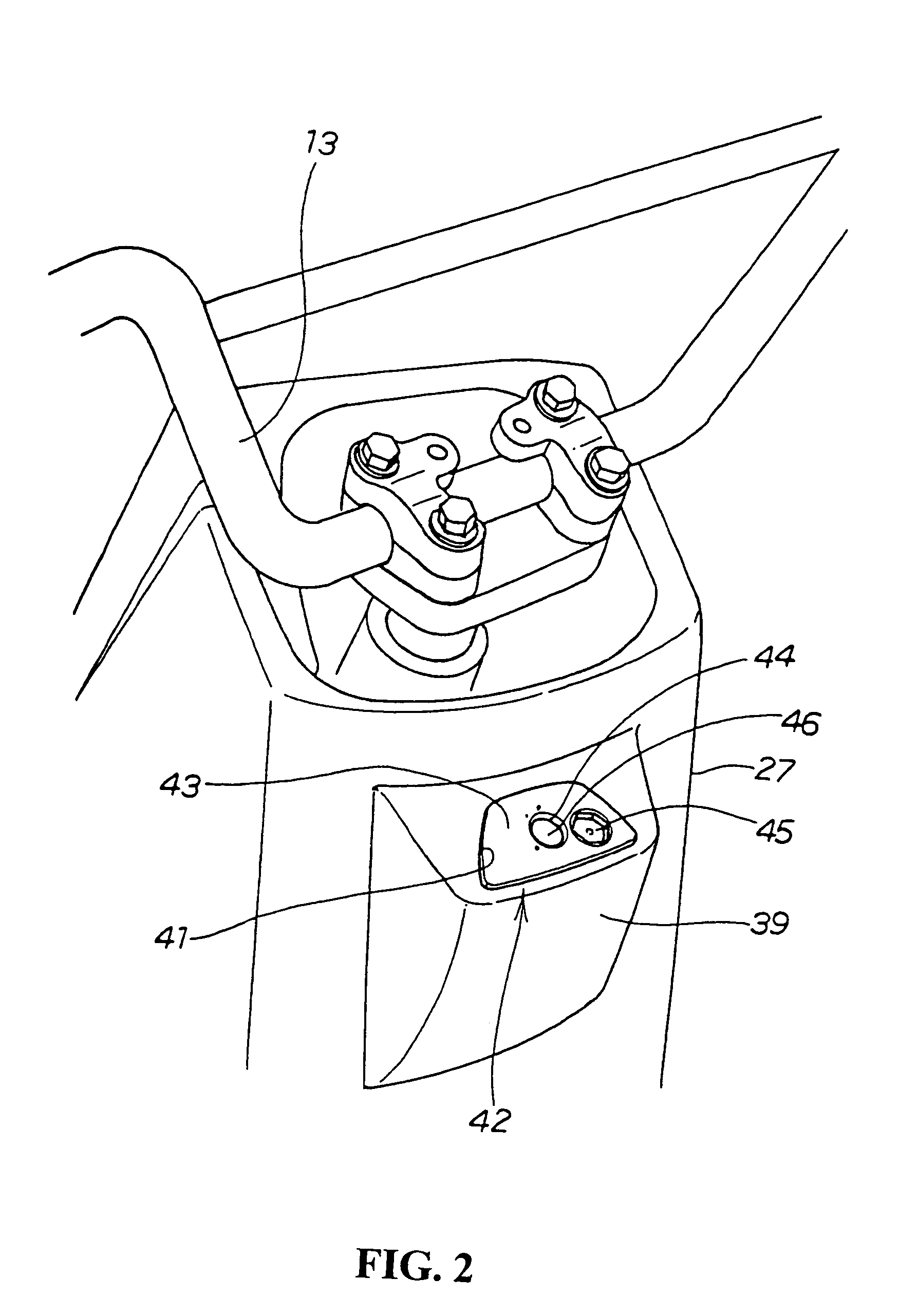
Since the bolts for fixing the shutter housing are attached from the back surface of the top plate of the inverted angular U-shaped bracket, even when a gap is generated between the shutter housing and the vehicle body cover, the bolts are not exposed and hence cannot be loosened easily.
In addition, since the bolts are screwed from the gaps between the side surfaces of the key cylinder unit and the legs, it is difficult to loosen these bolts from the outside.
In addition, since the upper surface and the both side surfaces of the key cylinder unit are covered by the inverted angular U-shaped bracket, even when an attempt is made to insert a rod-shaped object from the outside, the rod-shaped object can hardly reach a principal portion of the key cylinder unit in view of the protecting effect of the inverted angular U-shaped bracket.

Method used


Image

  • Vehicle provided with key cylinder device equipped with handle lock mechanism
  • Vehicle provided with key cylinder device equipped with handle lock mechanism
  • Vehicle provided with key cylinder device equipped with handle lock mechanism

Examples


Embodiment Construction

[0028]Referring now to the attached drawings, an embodiment of the preset invention will be described below.

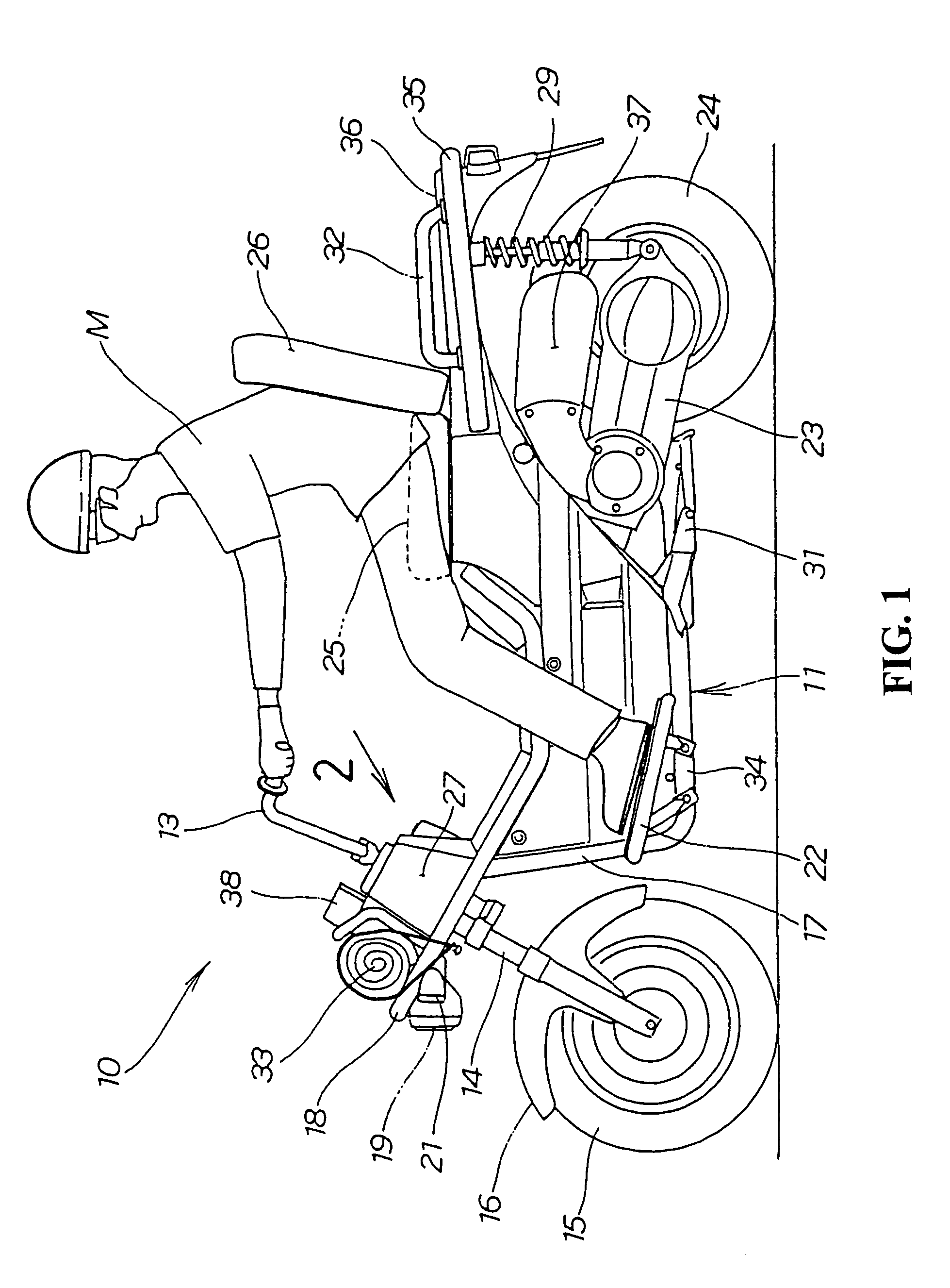
[0029]In the present embodiment, a scooter-type vehicle will be described as an example. The vehicle, however, may be any type of two-wheeler, three-wheeler and four-wheeler vehicle as long as it has a front wheel and a rear wheel provided at the front and rear of a vehicle body frame, and a steering handle that is steerably attached to a head pipe of the vehicle body frame.

[0030]FIG. 1 is a side view of a scooter-type vehicle according to the present invention, in which a scooter-type vehicle 10 is a two-seater light-weight vehicle including a steering handle 13 steerably mounted at the front of a vehicle body frame 11 with a front wheel 15 and a front fender 16 mounted to a front fork 14 to be connected to the steering handle 13. A separate frame 18 is attached to the vehicle body frame 11 with a headlamp 19, turn signal lamps 21 etc. being attached to the separate frame 18....


PUM


Abstract

To provide a key cylinder device equipped with a handle lock mechanism which can maintain a handle lock mechanism of a key cylinder unit with a shutter to provide an improved assembleability of the key cylinder device. The bolts for fixing a shutter housing are attached from the back surface of the top plate of an inverted angular U-shaped bracket. Thus, even when a gap is generated between the shutter housing and a vehicle body cover, the bolts are not exposed and hence cannot be easily loosened. In addition, by mounting the key cylinder device in the vehicle body cover and then mounting the vehicle body cover thereon, assembleability can be improved.

Description

CROSS-REFERENCE TO RELATED APPLICATIONS[0001]The present application is related to Japanese Patent Application No. 2003-209733 filed on Aug. 29, 2003 the entire contents of which are hereby incorporated by reference.BACKGROUND OF THE INVENTION[0002]1. Field of the Invention[0003]The present invention relates to an improved key cylinder device equipped with a handle lock mechanism suitable for a motorcycle.[0004]2. Description of the Background Art[0005]In the related art, a key cylinder device equipped with a handle lock mechanism having a shutter is proposed, for example in JP-A-11-44132, see FIG. 2.[0006]FIG. 7 of the present application is a drawing corresponding to FIG. 2 in JP-A-11-44132, in which a reference symbol Bc and a reference symbol C are added.[0007]A cylinder lock 1 has a structure including a rotor 3 rotatably stored in a cylinder body 2 with a lock bar 8 connected to a camshaft 6 at a lower part of the rotor 3. A substantially cap-shaped ring 12 is covered on the c...

Claims


Application Information

Patent Timeline
Patent Type & Authority Patents(United States)
IPC IPC(8): B60R25/02B62H5/02B62H5/06B62K21/00E05B71/00E05B83/00
CPCB60R25/02126B62H5/02E05B71/00B60R2325/306Y10T70/5664Y10T70/5872Y10T70/7955Y10T70/8622
Inventor NAKAI, SHINMICHISAKA, SUSUMU
Owner HONDA MOTOR CO LTD
Learn More