Indwelling catheter

a catheter and intubation technology, applied in the field of intubation catheters, can solve the problems of complicated structure of the hemostasis valve made of two components, dead space becomes, etc., and achieve the effect of reducing the risk, simplifying the structure of the hemostasis valve, and reducing the dead space in the female connector

Inactive Publication Date: 2008-03-25
NIPRO CORP
View PDF10 Cites 94 Cited by
  • Summary
  • Abstract
  • Description
  • Claims
  • Application Information

AI Technical Summary

Benefits of technology

[0008]An object of the invention is to provide an indwelling catheter in which the structure of a hemostasis valve is simplified to reduce a dead space in a female connector and reduce the risk that the dead space becomes a cause of the onset of infectious diseases, as well as in which even if connecting operation is repeated, there is not a great risk that the function of the hemostasis valve is impaired.

Problems solved by technology

Accordingly, during the connecting operation, if microorganisms enter by accident, the dead space becomes a breeding ground of various microorganisms, so that there is the risk that the dead space becomes a cause of the onset of infectious diseases.
In addition, there is also the problem that the hemostasis valve has a complicated structure made of two component parts.

Method used


Image

  • Indwelling catheter
  • Indwelling catheter
  • Indwelling catheter

Examples


first embodiment

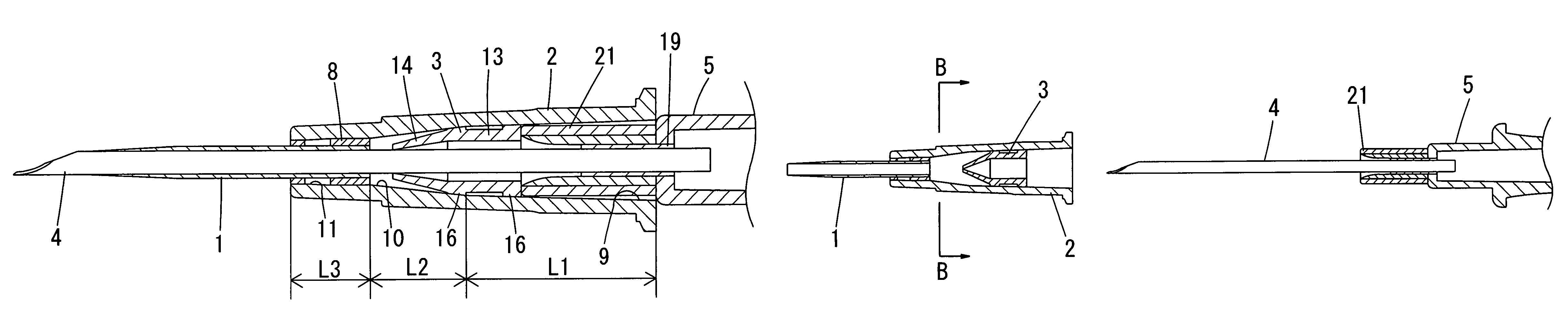
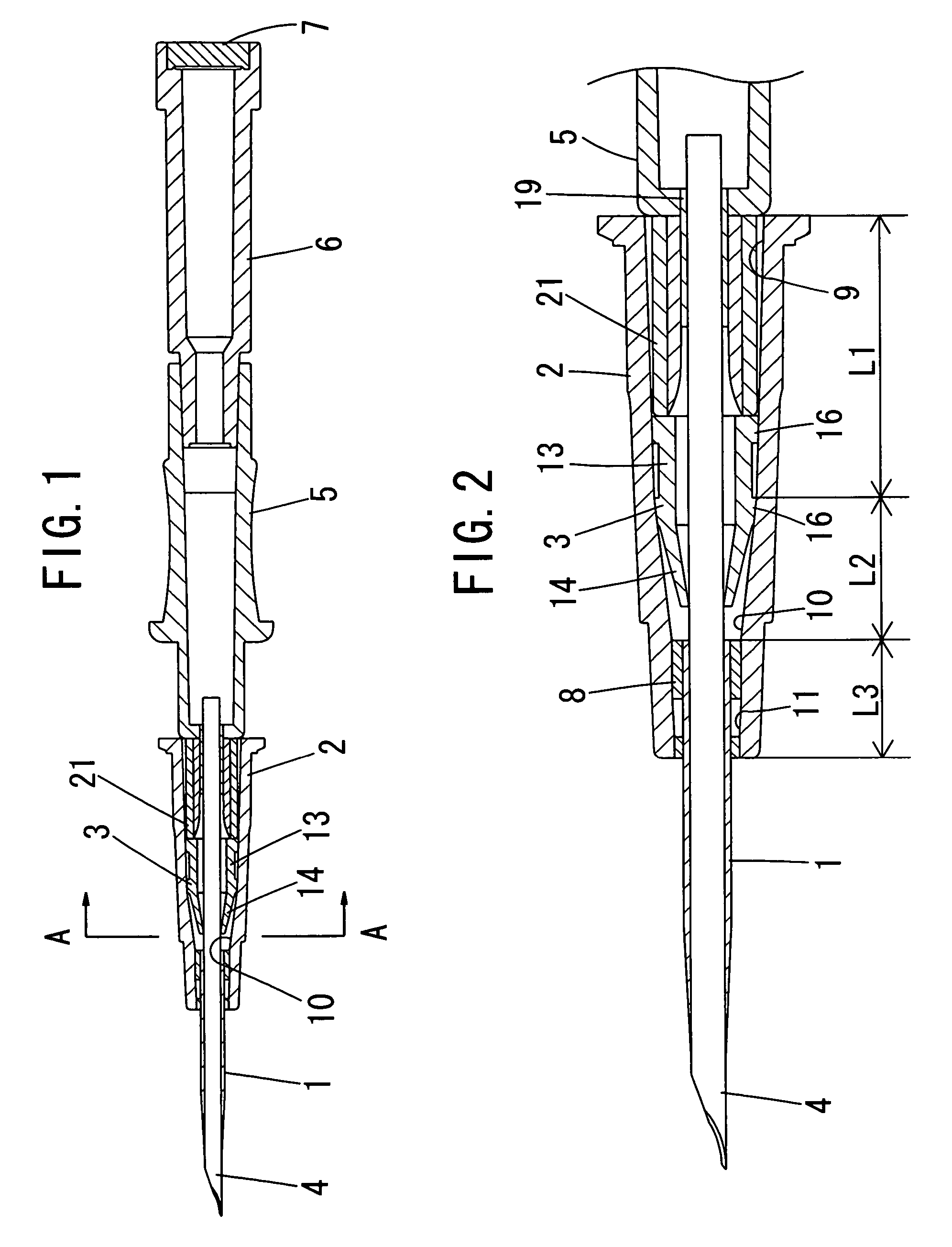
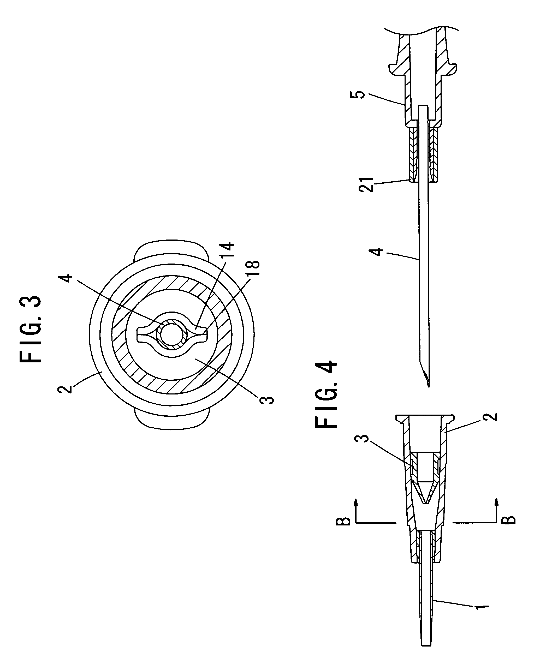
[0058]A first embodiment in which the invention is applied to an external needle type indwelling catheter will be described with reference to FIGS. 1 to 9. FIG. 1 shows a catheter, and the catheter has a tube (a catheter tube, an external needle) 1, a female connector (a catheter connector, an external needle hub) 2, a hemostasis valve 3, an inner needle (a hollow needle) 4, an inner needle hub 5, a filter cap 6, a hydrophobic filter 7, and the like.

[0059]As shown in FIGS. 2 to 9, the tube 1 is elongated and (semi)transparent and has flexibility, and is integrally molded from a plastic (resin) material and is arranged in the longitudinal direction. As this plastic material, for example, a thermoplastic resin is used. As this thermoplastic resin, various materials can preferably be enumerated, such as ethylene-tetrafluoroethylene copolymers (ETFE), tetrafluoroethylene-perfluoroalkylether copolymers (PFA), polypropylene resins, polyethylene resins, polyvinyl chloride, acrylonitrile-bu...

second embodiment

[0083]According to the above-described second embodiment, when fluid is transfused or blood is drawn from a blood vessel such as a peripheral vein in the back of a hand of a patient or from under the skin or the like of the patient, first of all, as shown in FIGS. 10 and 11, the inner needle 4 and the inner needle hub 5 of the catheter are inserted into the female connector 2 from the rear. The inner needle 4 is inserted through the tube 1 while the slit 15 of the openable / closable portion 14 of the hemostasis valve 3 is being pressed open due to elastic deformation by the inner needle 4, and the inner needle hub 5 presses the hemostasis valve 3 toward the front. Accordingly, the tubular portion 12 of the hemostasis valve 3 is elastically deformed toward the front and reduced in size, and the openable / closable portion 14 is elastically deformed to a further extent in the radially outward direction by the abutment between the openable / closable portion 14 and the rear end of the conne...


PUM


Abstract

An indwelling catheter comprises a tube, a female connector and an elastically deformable hemostasis valve which can be pressed by a male connector. An opening taper portion tapered forwardly is formed in a longitudinal intermediate portion of an inner circumferential surface of the female connector. The elastically deformable hemostasis valve is provided longitudinally slidably in the opening taper portion of the female connector and an inside portion extending rearwardly from the opening taper portion. The hemostasis valve includes; a body having a hollow form opened at its front and rear ends or a tubular portion fitted over the connecting portion from a rearward direction; and an openable / closable portion being opened by elastic deformation of the body or the tubular portion.

Description

FIELD OF THE INVENTION[0001]The present invention relates to improvements in a connector portion of an indwelling catheter which is left implanted in an artery, a vein and the like and is used for infusion, blood transfusion, artificial dialysis and the like, and more specifically, to a catheter which is improved in a connection operation and is capable of, when left implanted in an artery, a vein and the like, preventing the leakage of blood from the catheter until a cap or a infusion line is connected to the catheter.DESCRIPTION OF THE RELATED ART[0002]There is heretofore been an indwelling catheter of the type which includes a female connector connected to a tube to be left implanted in an artery, a vein and the like; and a homostasis valve which is provided in this female connector comprises a body having a slit and being fitted in the female connector and a pusher provided for slidable movement in the female connector and operative to press and open the slit of the body (refer ...

Claims


Application Information

Patent Timeline
Patent Type & Authority Patents(United States)
IPC IPC(8): A61M5/178A61M39/06A61M39/26
CPCA61M39/0606A61M39/26A61M2039/0633A61M2039/0646
Inventor HIEJIMA, KATSUHIRO
Owner NIPRO CORP
Why Eureka
Try Eureka