
Advanced current control method and apparatus for a motor drive system

a technology of motor drive and current control method, which is applied in the direction of dynamo-electric machines, ac commutators, dc motor speed/torque control, etc., can solve problems such as system stability problems, voltage limitation, and not being likely to be m

Active Publication Date: 2008-03-25
HONEYWELL INT INC
View PDF15 Cites 42 Cited by
  • Summary
  • Abstract
  • Description
  • Claims
  • Application Information

AI Technical Summary

Benefits of technology

The present invention is an apparatus and method for controlling a power converter of an AC motor drive system. The apparatus selects an operation mode for the motor based on real-time operating conditions and generates a current control reference value to achieve current control under various operating conditions. The method controls the output of multi-phase AC current from the power converter to the motor in accordance with the selected operation mode. The technical effect of the invention is to improve the efficiency and performance of AC motor drive systems by optimizing current control under various operating conditions.

Problems solved by technology

This condition is not likely to be met in aerospace applications, because a voltage limitation will typically be exerted on the system to achieve maximum power density and efficiency.
With such voltage constraints, not only will the system operating point drift off from the desired state, but the system may encounter stability problems when using a vector control method.
The voltage limitation can also come from abnormally low DC bus or DC bus disturbances introduced by system dynamics, such as power interruptions.
The system will typically experience other unexpected transient situations, e.g., caused by load dynamics or by noise, errors and spikes due to inverter, controller and motor non-idealities.
This means a trade-off with over-all system size and weight, however, which is undesirable.

Method used


Image

  • Advanced current control method and apparatus for a motor drive system
  • Advanced current control method and apparatus for a motor drive system
  • Advanced current control method and apparatus for a motor drive system

Examples


Embodiment Construction

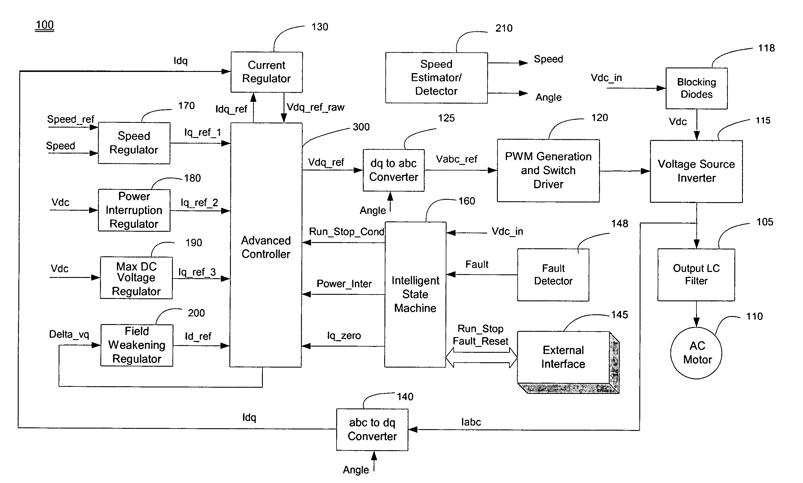
[0015]As will be described in detail below, an embodiment of the present invention performs advanced current control to effectively control a power inverter of an AC motor drive, using an intelligent control technique to optimize motor drive system operation under a variety of normal / abnormal operating conditions. An embodiment of the present invention recognizes and categorizes different system operating conditions, and chooses an operation mode based on these operating conditions so that the motor controller can effectively and dynamically operate to satisfy motor system performance requirements. Using this control technique, the motor drive system operation is optimized, robust, and reliable.

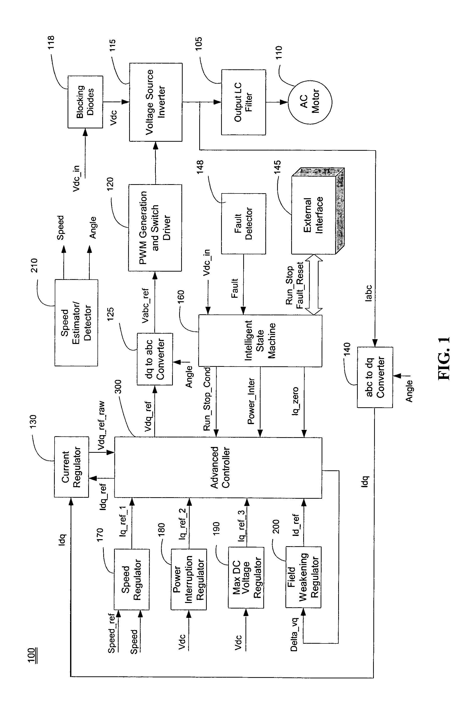
[0016]FIG. 1 is a block diagram illustrating an AC motor drive system in which principles of the present invention are applied to achieve advanced current control according to an embodiment of the present invention. An exemplary environment for this embodiment is an aircraft motor system, alt...


PUM


Abstract

An apparatus controls a power converter of an AC motor drive system, the power converter outputting multi-phase AC current to an AC motor. The apparatus comprises: a state selecting unit; and an advanced controller. The state selecting unit selects an operation mode, from among a plurality of operation modes, for the AC motor based on system real-time operating conditions, the plurality of operation modes including a normal mode, a power interruption mode, a fault protection mode, and a power-up / down dynamic mode. The system operating conditions include DC voltage available to the power converter, motor load condition, and motor speed command. The advanced controller controls multi-phase AC current output from the power converter to the motor in accordance with the operation mode selected by the state selecting unit. The advanced controller generates a current control reference value that is based on the selected operation mode to achieve current control under various operating conditions of the motor drive system.

Description

CROSS-REFERENCE TO RELATED APPLICATION[0001]The present application claims priority under 35 U.S.C. §119(e) to U.S. Provisional Application No. 60 / 631,543, filed Nov. 30, 2004, which is incorporated by reference herein in its entirety.FIELD OF THE INVENTION[0002]The present invention relates to motor drive system technology, and more particularly to an advanced current control method and apparatus for a motor drive system for controlling motor operation under a variety of normal / abnormal operating conditions.BACKGROUND OF THE INVENTION[0003]Aerospace applications require more robust and more reliable motor drive systems with high power density and high operation efficiency (more compact in size and weight). These requirements are even more critical for the newly developing “more electrical aircraft”, for its much higher electrical power ratings and much larger number of AC motor drive systems on board. A conventional AC motor drive system utilizes an inverter (e.g., a voltage source...

Claims


Application Information

Patent Timeline
Patent Type & Authority Patents(United States)
IPC IPC(8): H02P27/04
CPCH02P21/0032H02P21/0089H02P21/0092H02P27/00H02P29/02H02P29/021H02P21/00H02P21/34H02P21/36H02P29/0241
Inventor MA, JACKZHOU, GEORGEWANG, ZHENG
Owner HONEYWELL INT INC
Learn More