
Vehicle control

a technology for vehicles and control systems, applied in the direction of process and machine control, instruments, etc., can solve the problems of less than optimal stability, handling, safety performance of vehicles, complicated and confusing control systems, etc., and achieve the effect of improving the control of vehicles

Active Publication Date: 2008-03-25
JAGUAR LAND ROVER LTD
View PDF15 Cites 288 Cited by
  • Summary
  • Abstract
  • Description
  • Claims
  • Application Information

AI Technical Summary

Benefits of technology

[0008]The present invention aims to provide a vehicle control system which can be operated so as to provide improved control of the vehicle on a broader range of surfaces, and in particular in a plurality of different off-road surfaces and terrains such as might be encountered when driving off-road.
[0017]Preferably one of the subsystems comprises a yaw control system which is arranged to control vehicle yaw, and said plurality of subsystem configuration modes allow different levels of divergence of said vehicle yaw from an expected yaw.
[0034]Preferably the roll control system is arranged to provide a higher roll stiffness in the on-road mode than in the off-road mode.
[0038]Preferably the traction control system allows higher levels of wheel spin in the high friction mode than in the low friction mode.
[0048]Preferably one of the modes is a sand mode in which the subsystems are controlled in a manner suitable for driving on sand. Preferably at least one of the subsystems is arranged, in the sand mode, to allow only relatively low levels of wheel spin when the vehicle is traveling at low speeds so as to avoid the vehicle wheels becoming submerged in sand, but to allow relatively high levels of wheel spin when the vehicle is traveling at higher speeds.
[0052]At least one of the modes may be a plough surface mode in which the brake control subsystem is arranged to allow a relatively high degree of wheel slip under braking. This is useful, for example on snow or sand, where the build up of matter in front of the wheels under braking can improve braking performance.

Problems solved by technology

Unless the driver is very experienced, this can become complicated and confusing.
Unfortunately, the operating characteristics of such an integrated control system does not provide the driver with the ability to provide direct input regarding the surface terrain in an attempt to better select the appropriate subsystem configuration modes.
This deficiency results in the less than optimal stability, handling, and safety performance of the vehicle.

Method used


Image

  • Vehicle control
  • Vehicle control
  • Vehicle control

Examples


first embodiment

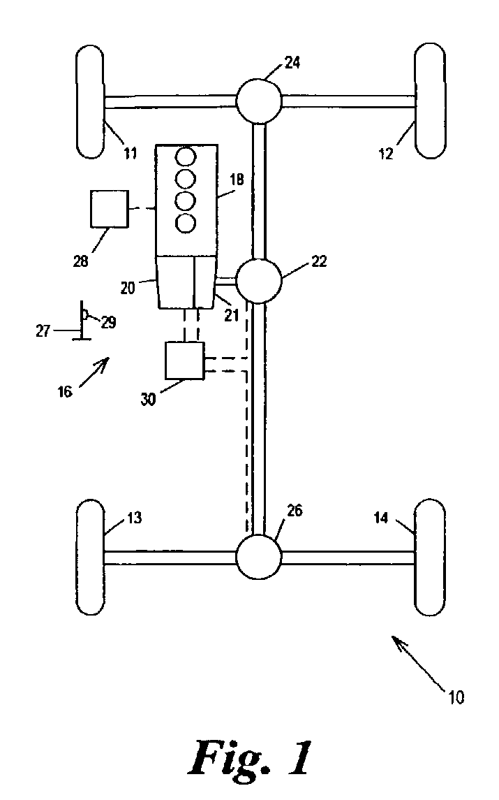
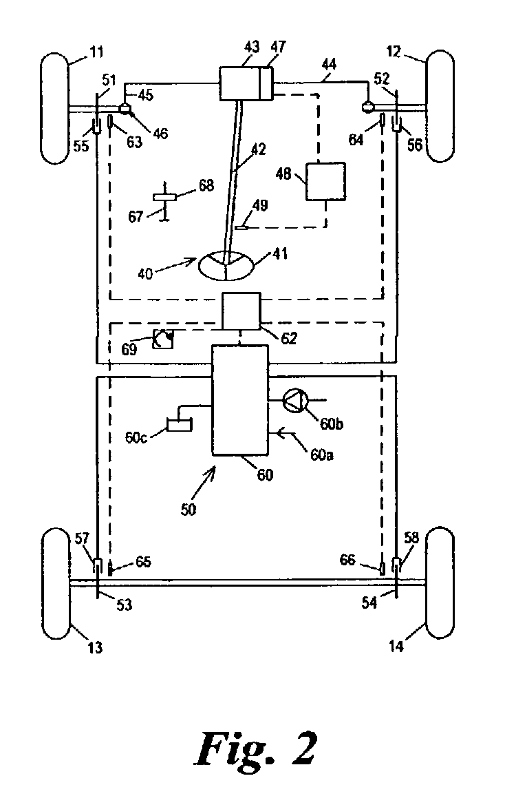
[0071]Referring to FIG. 1, according to the invention a vehicle 10 has four wheels 11, 12, 13, 14 and a powertrain 16 for providing driving torque to the wheels. The powertrain 16 comprises an engine 18, an automatic transmission 20 which transmits drive torque at any of a number of transmission ratios, via a transfer box 21 to the input side of a center differential 22. Front and rear differentials 24, 26 receive torque from the center differential 22 and transmit it to the front wheels 11, 12 and rear wheels 13, 14 respectively. An engine controller 28 in the form of an engine management system controls operation of the engine 18 so as to control its speed and output power and torque in response to inputs from the driver from a throttle pedal 27, the position of which is measured with a throttle pedal position sensor 29. A transmission controller 30 controls the transmission ratio of the automatic transmission 20, and the selection of high or low range in the transfer box 21. It a...

second embodiment

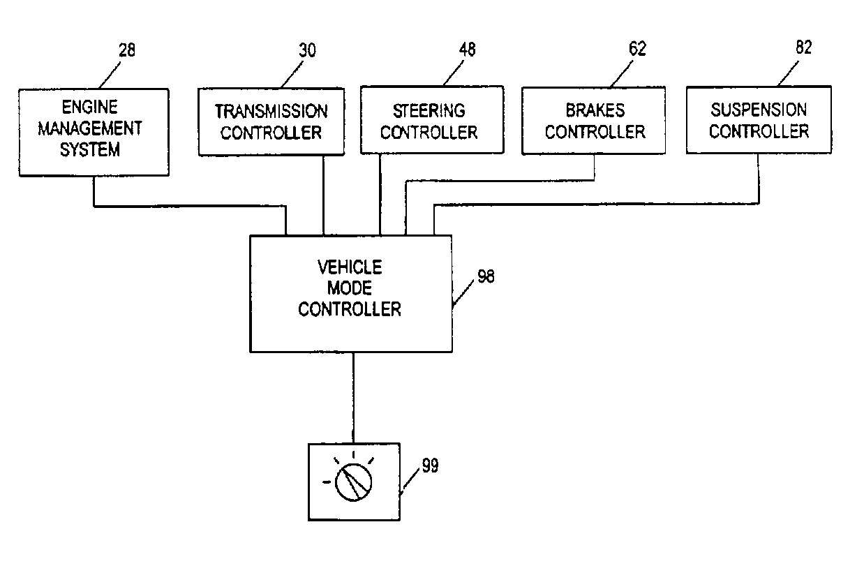
[0102]In the second embodiment the functions which are controlled by the vehicle mode controller 98 are the throttle pedal characteristic, the gear changes in the transmission 20, the locking torque of the center and rear differentials 22, 26, the traction control function, the yaw control function provided by the D.S.C. system, the air suspension ride height, the suspension cross linking, and the hill descent control function. The hill descent control defines a target speed and uses the brakes to control the vehicle speed to the target speed as the vehicle descends a hill. The target speed has a default value which is nominally 6 kph, but can be increased by depressing the accelerator pedal 27 and decreased by depressing the brake pedal down to a minimum value of 3 kph. The default target speed can be varied depending on the mode selected. The differential controller 30 is also arranged to receive inputs from the steering angle sensor 49 and the ride height sensors 83, 84, 85, 86, ...

third embodiment

[0112]Referring to FIG. 13, in the invention the driving mode in which the vehicle operates is determined by two separate inputs. One input, a rotary terrain knob 100, allows the user to input the type of terrain over which the vehicle is being driven. The other input, a rotary “mode of use” knob 102 allows the user to input the mode in which the vehicle is to be used. This can include vehicle modes relating to the manner in which the vehicle is to respond to the driver's inputs, such as a sport mode or an economy mode, as well as modes relating to the state of the vehicle, such as a towing mode suitable for towing a trailer, and a laden mode for when the vehicle is carrying a particularly heavy load. In this example the vehicle “mode of use” knob allows selection of normal, sport, and towing vehicle driving modes. The sport driving mode is adapted for use when the vehicle is being driven in a “sporty” manner, characterized for example by one or more of: rapid acceleration and braki...


PUM


Abstract

A vehicle control system has a plurality of subsystem controllers including an engine management system 28, a transmission controller 30, a steering controller 48, a brakes controller 62 and a suspension controller 82. These subsystem controllers are each operable in a plurality of subsystem modes, and are all connected to a vehicle mode controller 98 which controls the modes of operation of each of the subsystem controllers so as to provide a number of driving modes for the vehicle. Each of the modes corresponds to a particular driving condition or set of driving conditions, and in each mode each of the functions is set to the function in mode most appropriate to those conditions.

Description

BACKGROUND OF INVENTION[0001]1. Field of the Invention[0002]The present invention relates to the control of vehicles, in particular to the coordinated control of a number of subsystems of a vehicle.[0003]2. Background Art[0004]Various systems are known in which operation of various subsystems of a vehicle can operate in different configuration modes so as to suit different conditions. For example, automatic transmissions can be controlled in sport, winter, economy and manual configuration modes in which the changes between gear ratios and other subsystem control parameters are modified so as to suit the prevailing conditions or the taste of the driver. Air suspensions are known with on-road and off-road configuration modes. Stability control systems can be operated at reduced activity so as to give the driver more direct control over the operation of the vehicle. Power steering systems can be operated in different configurations modes where the level of assistance is at different le...

Claims


Application Information

Patent Timeline
IPC IPC(8): G06F17/00B60G17/0195B60K17/346B60K17/35B60K23/08B60K28/16B60T8/58B60W30/18B60W50/00
CPCB60G17/0195B60K28/16B60K28/165B60K41/282B60T8/58B60W10/06B60W10/11B60W10/20B60W10/22B60W30/18B60W50/082B60G2600/20B60G2800/85B60G2800/91B60G2800/92B60G2800/96B60G2800/97B60K17/3462B60K17/35B60K23/0808B60K2741/283B60K2741/286B60T2201/04B60T2220/02B60T2260/08B60W2050/0063B60W2520/14B60W2540/04B60W2540/30B60W2550/14B60W2550/141B60W2550/142F16H2300/14Y02T10/84B60W2552/00B60W2540/215B60W2552/05B60W2552/15B60W50/085B60W30/182B60W2552/35
Inventor SPILLANE, ANTHONY FRANCISBURDOCK, WILLIAMCLARE, DAVID ANDREWJONES, DEREK LESLIEKELLETT, JOHN ANTHONYPRINS, JAN PIETERPARSONS, KEITH GARY REGINALDDARNELL, PAUL MALCOLM
Owner JAGUAR LAND ROVER LTD
Learn More