
Tightly coupled accelerator

a technology of tight coupling and accelerator, applied in the field of data processing systems, can solve the problems of inability to write and test inability to design, test and validate accelerators, and additional effort to be expended in writing and testing individual versions of computer programs, so as to improve the degree of potential functionality of the accelerator unit, save hardware overhead, and simplify the design and use of the accelerator.

Active Publication Date: 2008-03-25
ARM LTD +1
View PDF24 Cites 12 Cited by
  • Summary
  • Abstract
  • Description
  • Claims
  • Application Information

AI Technical Summary

Benefits of technology

The present invention provides an apparatus for processing data under control of a program with program instructions. The apparatus includes an operand store for storing operand data, an execution unit for performing data processing operations, and an accelerator unit for performing accelerated data processing operations. The accelerator unit is configurable using predetermined sets of configuration data to execute specific computational subgraphs. The apparatus can save hardware resources by not writing intermediate operand values to the operand store. The accelerator unit can be designed to support multiple computational subgraphs without requiring individual specific hardware for each one. The accelerator unit can include a plurality of primitive operator units and interconnections between them to perform different processing operations. The invention provides a flexible and effective form of the accelerator unit for processing data.

Problems solved by technology

One problem with the approach of adding special purpose accelerators for particular computational subgraphs is that the effort in designing, testing and validating those accelerators must be repeated whenever a different form of computational subgraph is identified for acceleration.
Furthermore, the use of special purpose instructions in place of the instructions which would otherwise form the computational subgraph renders the program code incompatible with systems which do not include the special purpose accelerator.
Thus, additional effort must be expended in writing and testing individual versions of a computer program to operate on different hardware platforms.
The accelerated execution of the computational subgraph as a whole within such a tightly coupled arrangement can give rise to problems due to a lack of register resources within the system.

Method used


Image

  • Tightly coupled accelerator
  • Tightly coupled accelerator
  • Tightly coupled accelerator

Examples


Embodiment Construction

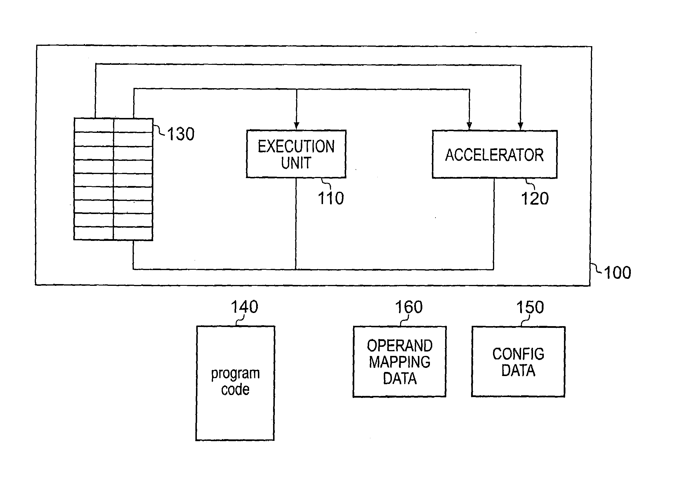
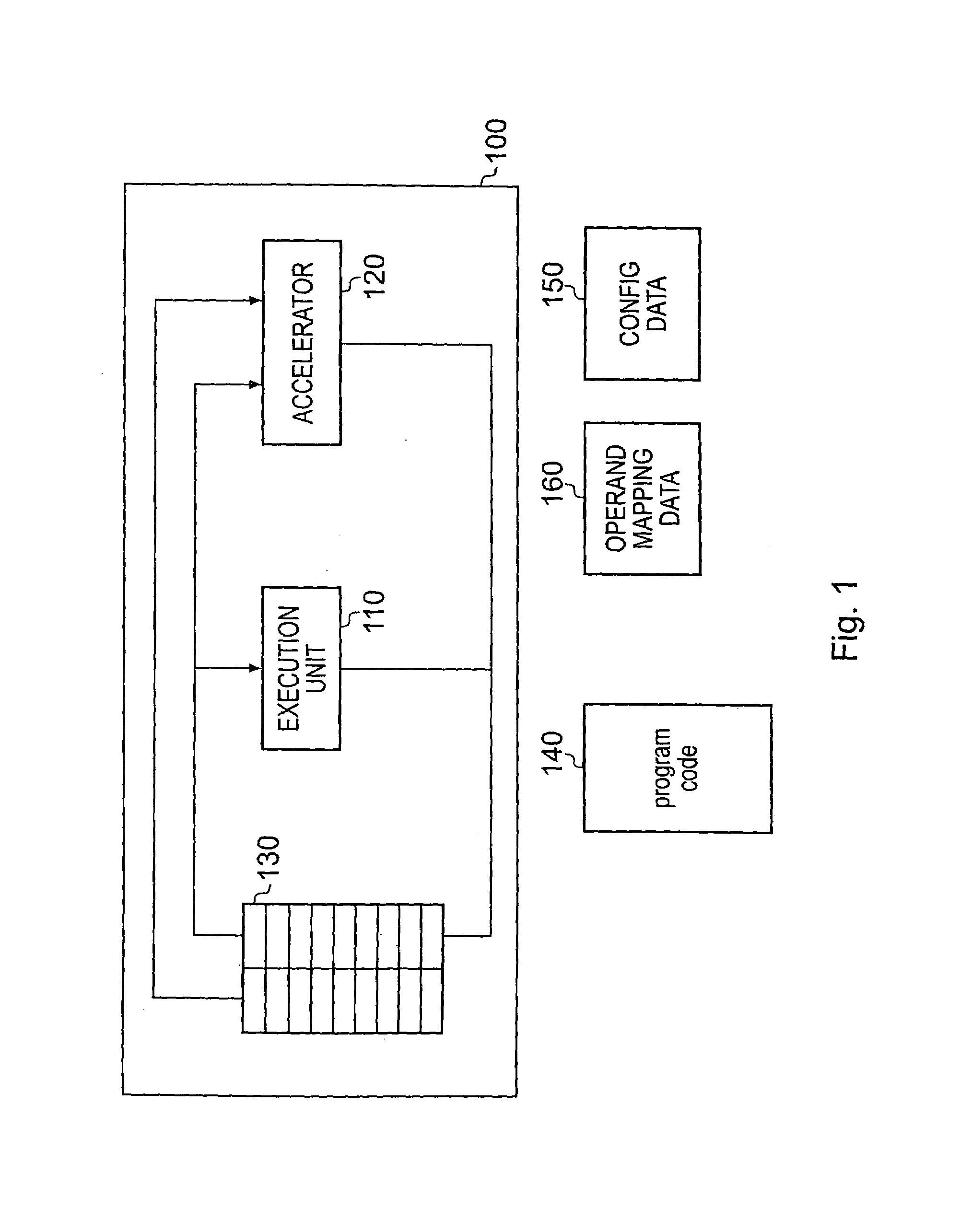
[0052]FIG. 1 schematically illustrates an information processor according to the present technique. The system comprises a processor core 100 having an execution unit 110, an accelerator 120 and a register bank 130. The processor core is operable to execute program code 140, a portion of which is executed using the execution unit 110 and another portion of which is executed using the accelerator 120 in dependence upon a set of configuration data 150 and set of operand mapping data 160. The accelerator 150 is connected in parallel to both the execution unit 110 and the register bank 130.

[0053]The accelerator 120 comprises an array of functional units that are configurable in dependence upon characteristics of the particular portion of program code to be executed by the accelerator 120. The accelerator 120 is configured in dependence upon the configuration data 150 to execute a series of separate program instructions corresponding to a particular computational subgraph of the computer...


PUM


Abstract

An accelerator 120 is tightly coupled to the normal execution unit 110. The operand store, which could be a register file 130, a stack based operand store or other operand store is shared by the execution unit and the accelerator unit. Operands may also be accessed as immediate values within the instructions themselves. The sequences of individual program instructions corresponding to computational subgraphs remain within a program but can be recognized by the accelerator as suitable for acceleration and when encountered are executed by the accelerator instead of by the normal execution unit. Within such tightly coupled arrangement problems can arise due to a lack of register resources within the system. The present technique provides that at least some intermediate operand values which are generated within the accelerator, but are determined not to be referenced outside of the computational subgraph concerned, are not written to the operand store.

Description

[0001]This application claims priority from U.S. provisional patent application 60 / 619,949, filed Oct. 20, 2004, the entire content of which is incorporated herein by reference.BACKGROUND OF THE INVENTION[0002]This invention relates to the field of data processing systems. More particularly, this invention relates to the disposition and relationship of an accelerator to the other elements within a data processing system.[0003]It is known to provide data processing systems including accelerator units operable to accelerate the execution of processing tasks (e.g. standalone accelerators for an entire function) as well as accelerators for particular sequences of individual program instructions corresponding to computational subgraphs. As an example, accelerators may be provided which are targeted by special purpose instructions added to the instruction set to perform particular encryption or decryption processing operations which would otherwise require a sequence of individual program...

Claims


Application Information

Patent Timeline
Patent Type & Authority Patents(United States)
IPC IPC(8): G06F15/16
CPCG06F8/44G06F9/3005G06F9/30054G06F9/3806G06F9/3897G06F9/3885G06F9/3836G06F9/3858G06F9/323
Inventor BILES, STUART D.FLAUTNER, KRISZTIANMAHLKE, SCOTTCLARK, NATHAN
Owner ARM LTD
Learn More