
Waterfall spillway

a technology for spillways and waterfalls, applied in water cleaning, swimming pools, agriculture, etc., can solve the problems of insufficient strength of polymer waterfall spillways, limited size of waterfall spillways, and fatigue of waterfall spillways, so as to reduce the likelihood of spillways. , the structure of the spillway is improved, the effect of reducing the likelihood of spillways

Inactive Publication Date: 2008-04-01
OUWINGA DAVID M
View PDF9 Cites 4 Cited by
  • Summary
  • Abstract
  • Description
  • Claims
  • Application Information

AI Technical Summary

Benefits of technology

"The present invention provides a waterfall spillway system that is aesthetically pleasing and can have different lengths and shapes. The spillway is versatile because an infinite number of walls can be added to the core segment, and the walls can be arranged to form various shapes. Additionally, the improved structure of the spillway lessens the likelihood of the spillway breaking or fracturing because of the stresses associated with water flow or forces applied by the surrounding earth."

Problems solved by technology

Due to their polymeric construction, the size of these waterfall spillways is usually limited due to mold sizing constraints.
Oftentimes, polymeric waterfall spillways are not strong enough to withstand seasonal temperature variations as well as the forces imparted on them by the surrounding earth.
Consequently, the spillways can fatigue and crack after extensive use.
This structural limitation inhibits the adaptability of the waterfall spillway to varying terrain.

Method used


Image

  • Waterfall spillway
  • Waterfall spillway
  • Waterfall spillway

Examples


Embodiment Construction

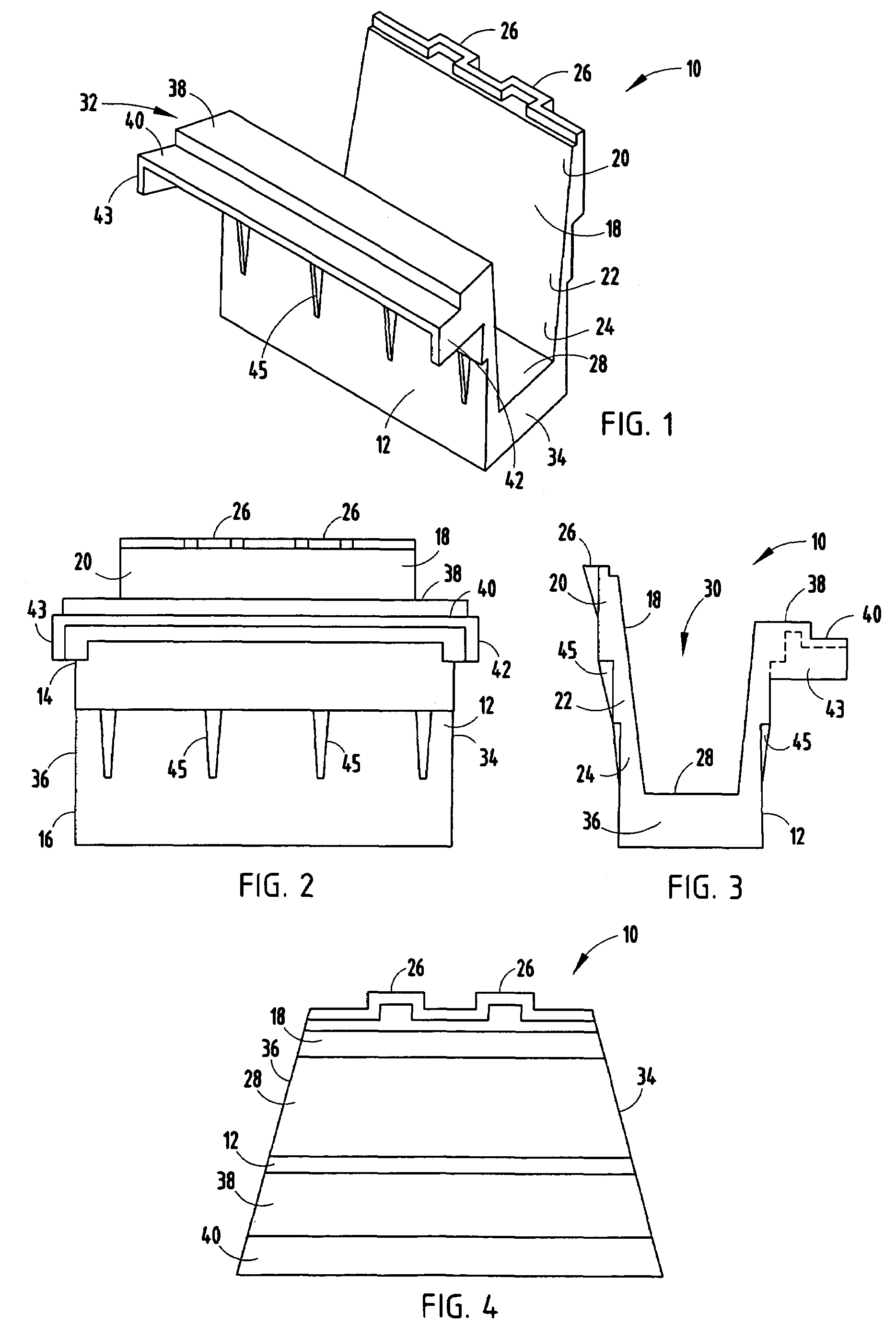
[0023]For purposes of description herein the terms “upper”, “lower”, “right”, “left”, “rear”, “front”, “vertical”, “horizontal” and derivatives thereof shall relate to the invention as oriented in FIG. 2. However, it is to be understood that the invention may assume various alternative orientations and step sequences, except where expressly specified to the contrary.

[0024]It is also to be understood that the specific devices and processes illustrated in the attached drawings, and described in the following specification are simply exemplary embodiments of the inventive concepts defined in the appended claims. Hence, specific dimensions and other physical characteristics relating to the embodiments disclosed herein are not to be considered as limiting, unless the claims expressly state otherwise.

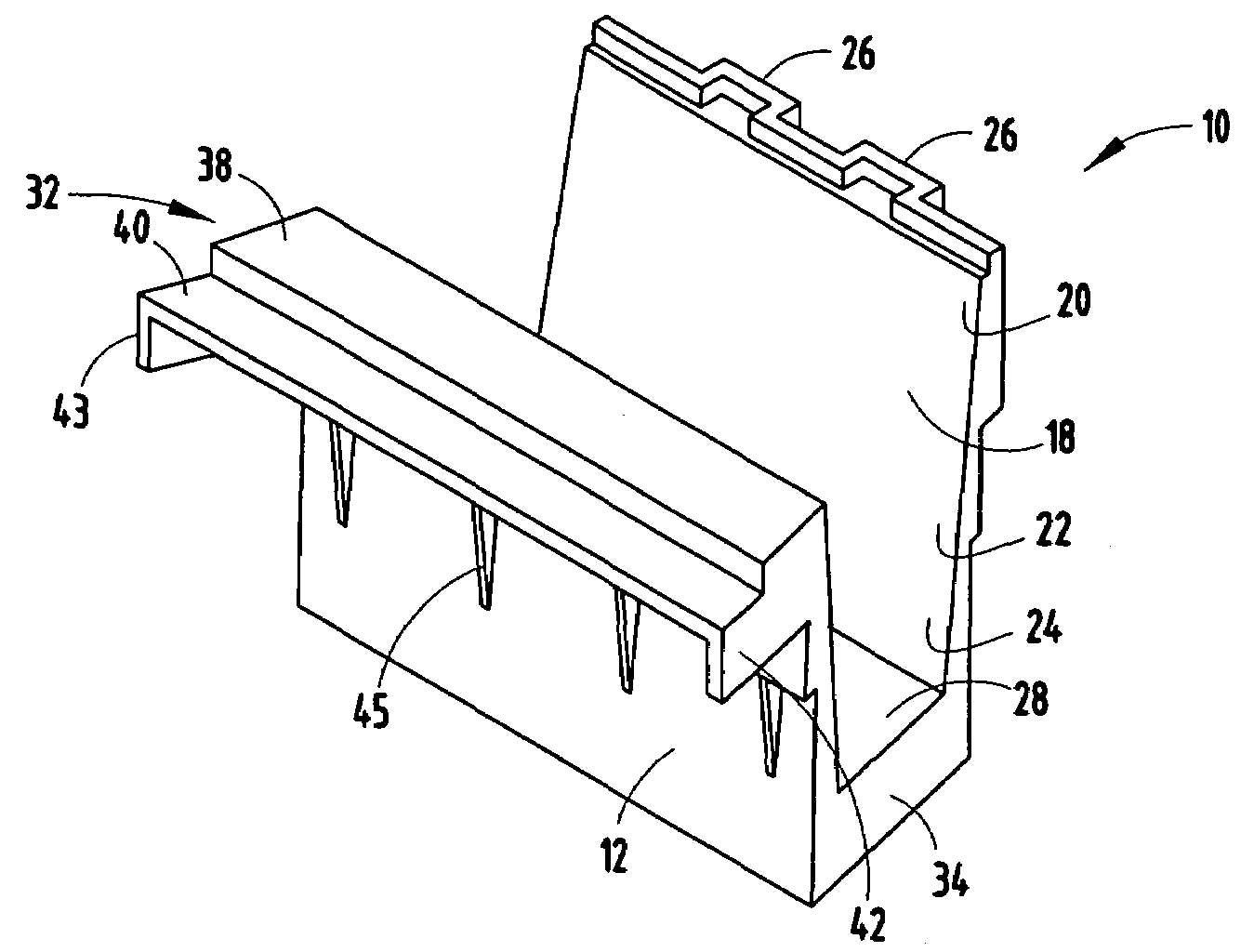
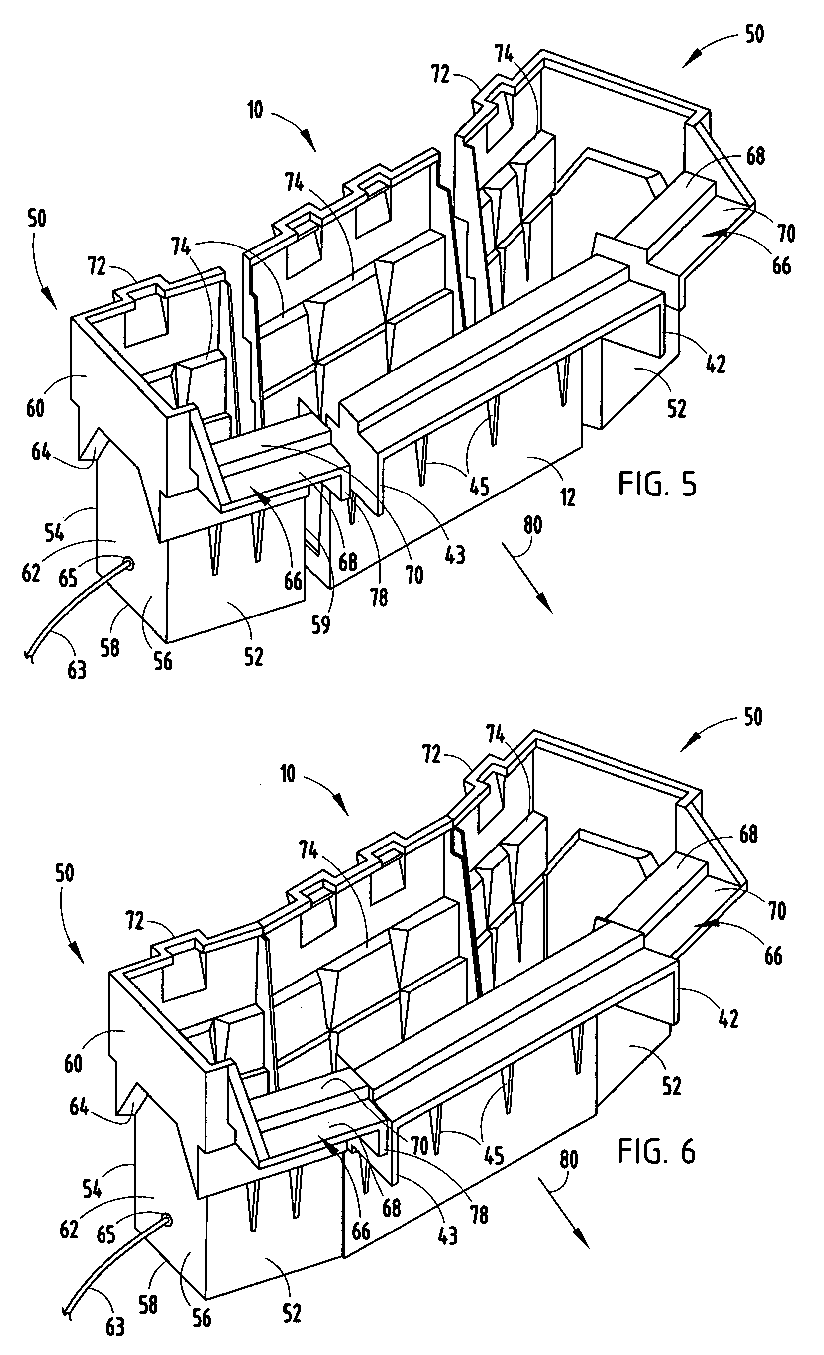
[0025]As illustrated in FIGS. 1-6, the reference numeral 10 generally designates a waterfall spillway embodying the present invention, which is designed for use in landscaping. The term “wate...


PUM


Abstract

A waterfall spillway is provided and has a front wall with a top portion and a bottom portion as well as a back wall substantially parallel with the front wall and having top, central, and bottom portions. A base wall is also included and connects the bottom portion of the front wall with the bottom portion of the back wall. A cavity is formed between the front wall and the back wall. A shelf extends from the top portion of the front wall, and is substantially parallel with the base wall. One or more of the side spillways may also be included.

Description

BACKGROUND OF THE PRESENT INVENTION[0001]The present invention relates to a waterfall spillway and the like and in particular to an expandable waterfall spillway having high strength characteristics and a method for making the same.[0002]Waterfall spillways must be versatile and capable of withstanding the pressures associated with continual water flow. These forces are frequently dissipated by the use of rocks, boulders, and aggregate which lessen the force exerted by water as it flows downward.[0003]Many man-made waterfall systems, including polymeric spillways, are designed to allow water to cascade downwardly while providing an aesthetic appearance. Due to their polymeric construction, the size of these waterfall spillways is usually limited due to mold sizing constraints. Oftentimes, polymeric waterfall spillways are not strong enough to withstand seasonal temperature variations as well as the forces imparted on them by the surrounding earth. Consequently, the spillways can fat...

Claims


Application Information

Patent Timeline
Patent Type & Authority Patents(United States)
IPC IPC(8): A01K63/04
CPCB05B17/08
Inventor OUWINGA, DAVID M.
Owner OUWINGA DAVID M
Learn More