Fluid-submerged electric motor

a technology of electric motors and electric motors, which is applied in the direction of positive displacement liquid engines, pumping machines, machines/engines, etc., can solve the problems of reducing the likelihood of localized hot spots in the motor, and achieves the effects of reducing the likelihood of localized hot spots

Active Publication Date: 2008-04-01
HAMILTON SUNDSTRAND CORP
View PDF8 Cites 33 Cited by
  • Summary
  • Abstract
  • Description
  • Claims
  • Application Information

AI Technical Summary

Benefits of technology

[0009]The present invention is directed to an electric starter having at least one electric motor component that is submerged in a cooling fluid held in a fluid-filled cavity. The stator, rotor, and rotor shaft bearings are all possible components that may be submerged. The cooling fluid floods the stator, rotor, and / or bearings to absorb heat from the components. The intimate contact between the fluid and the heat-generating components enhances heat dissipation because the fluid effectively absorbs and carries away heat from the components.
[0010]In one embodiment, the fluid has a high electrical resistance and also surrounds wires in the electric motor. In this way, the fluid can isolate the wires from any contact with flammable gasses as well as prevent arcs or sparks between wires. Further, the cooling effect of the fluid reduces the likelihood of localized hot spots in the motor.
[0011]The fluid may also act as a lubricant for the rotor shaft bearings. The cavity holding the fluid prevents the fluid from leaking or evaporating out of the motor, thereby ensuring continuous lubrication. This continuous fluid flow helps prevent abrasive wear particles from accumulating in the bearings.

Problems solved by technology

Further, the cooling effect of the fluid reduces the likelihood of localized hot spots in the motor.

Method used


Image

  • Fluid-submerged electric motor
  • Fluid-submerged electric motor
  • Fluid-submerged electric motor

Examples


Embodiment Construction

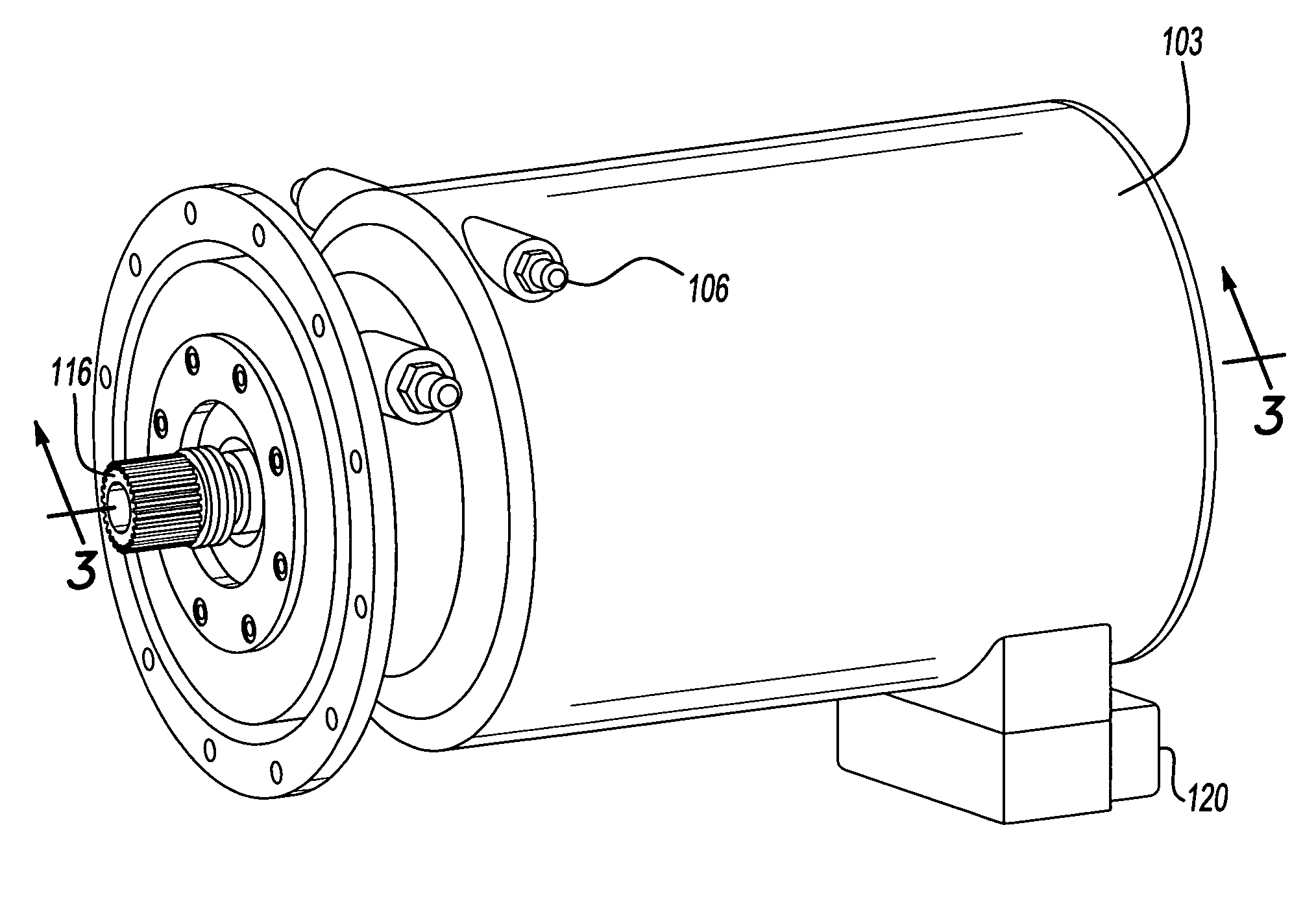
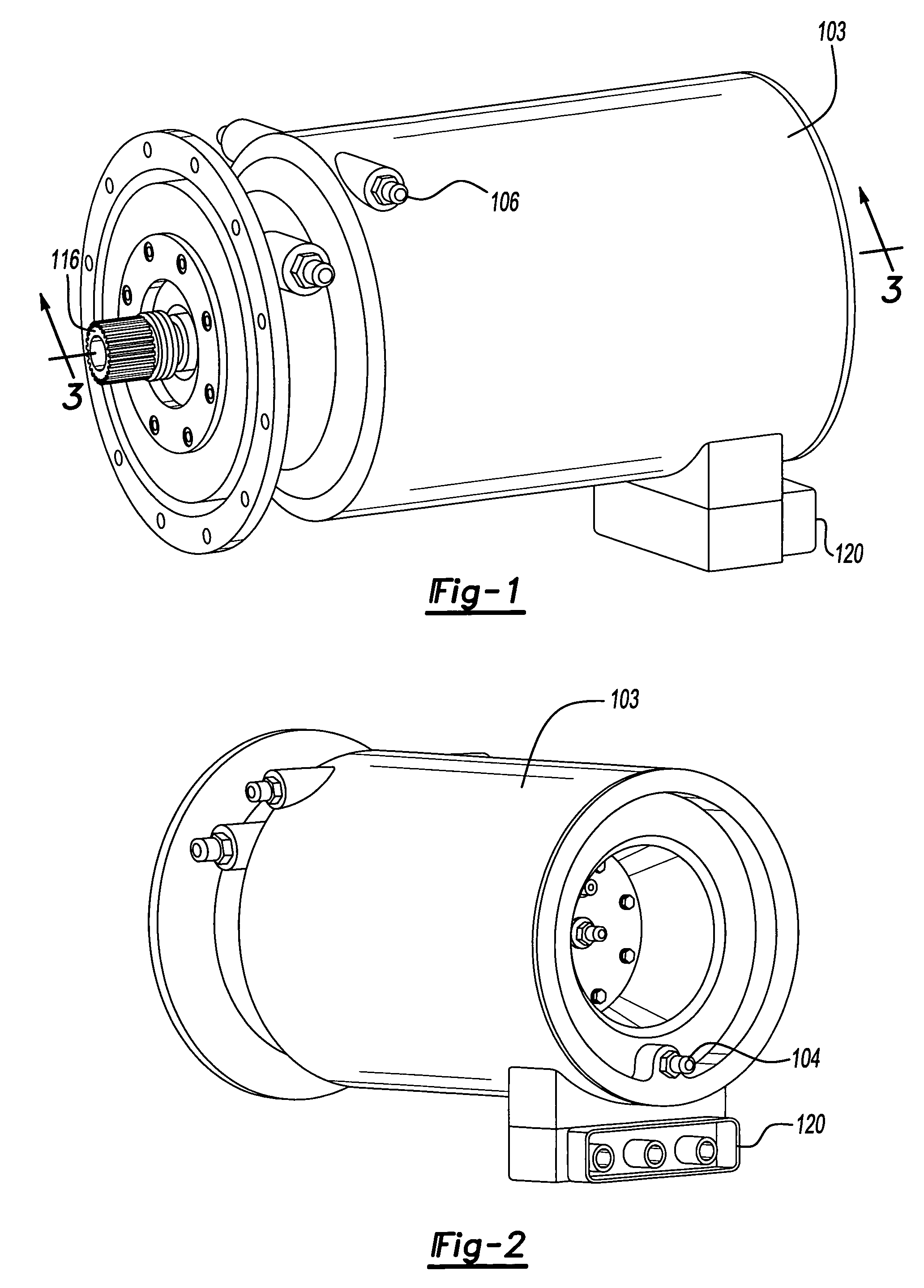
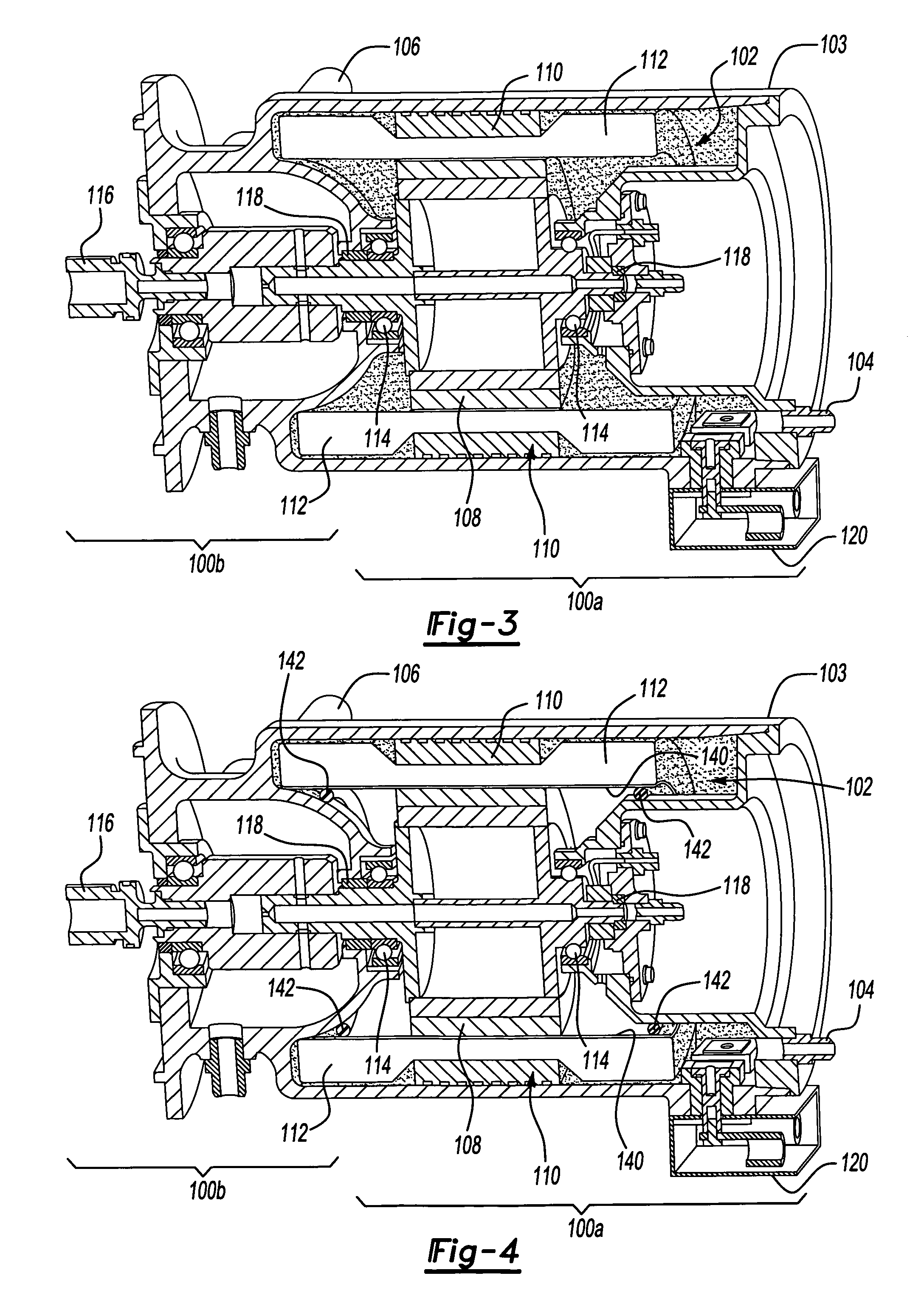
[0016]FIGS. 1 through 4 show an electric starter 100, having an electric motor 100a, such as a permanent magnet motor or switched reluctance motor, and a clutch 100b within a single package. In the embodiment shown in FIG. 3, the electric motor 100a is enclosed in a fluid-filled cavity 102 of a housing 103. The cavity 102 substantially encloses the motor 100a and has a fluid inlet 104 and a fluid outlet 106 to allow the fluid held in the cavity 102 to be circulated, removed and replaced when needed. The motor 100a itself can be any electric motor. As is known in the art, the motor 100a has a rotor 108, a stator iron 110, stator windings 112, and rotor bearings 114. The specific motor configuration does not affect the scope of the invention.

[0017]The cavity 102 can be filled with any fluid having heat conducting properties to ensure heat transfer from the motor components to the fluid. In one embodiment, the fluid is a dielectric oil, such as some commonly used synthetic gas turbine ...


PUM


Abstract

An electric motor has at least one component that is submerged in a cooling fluid held in a fluid-filled cavity. The stator, rotor, and rotor shaft bearings are all possible components that may be submerged. The cooling fluid floods the stator, rotor, and / or bearings to cool the components. The fluid may have a high electrical resistance to isolate the motor components from any contact with flammable gasses as well as prevent arcs or sparks. The cavity holding the fluid also ensures continuous lubrication by preventing fluid from leaking or evaporating out of the motor.

Description

TECHNICAL FIELD[0001]The present invention is directed to electric starters, and more particularly to starters having electric motors.BACKGROUND OF THE INVENTION[0002]Large-scale power generators often use gas turbine engines to supply power to a geographic region. Reliable start up of these engines is critical to ensure that power outages do not occur.[0003]Electric starters are known for starting small engines, but the special requirements of large engines have generally made them inappropriate for use with large engines. Many gas turbines in the 20 to 50 MW range are derivatives of aircraft engines (known as “aeroderivatives”) and, as such, they initially retained the lightweight, high-performance pneumatic starters from the initial design. As applications evolved, the pneumatic starters were replaced with hydraulic starters because weight is less of a concern in ground-based gas turbine engines. The next logical step is to apply electric motors to replace the hydraulic starter u...

Claims


Application Information

Patent Timeline
Patent Type & Authority Patents(United States)
IPC IPC(8): H02K9/00H02K5/128H02K5/136H02K7/14H02K9/19H02K9/197
CPCH02K5/136H02K7/14H02K9/197H02K5/128
Inventor GUSTAFSON, JAMES R.PARSONS, DOUGLASMARKS, KENNETH
Owner HAMILTON SUNDSTRAND CORP
Why Eureka
Try Eureka