Metal halide lamp and metal halide lamp lighting device with improved emission power maintenance ratio

a technology of metal halide lamps and lighting devices, which is applied in the direction of fixed installation, lighting and heating equipment, transportation and packaging, etc., can solve the problems of inability to use lamps as vehicle headlights, degraded detection accuracy, and high cost of cameras, so as to increase the emission power of light, reduce the energy of visible light flux, and reduce the sensitivity level

Inactive Publication Date: 2008-04-01
HARISON TOSHIBA LIGHTING CORP
View PDF29 Cites 1 Cited by
  • Summary
  • Abstract
  • Description
  • Claims
  • Application Information

AI Technical Summary

Benefits of technology

[0047]When the metal storing means is formed of a refractory metal doped with at least one metal selected from potassium (K), rubidium (Rb) and cesium (Cs), 10 to 200 μg of the at least one metal is added to 1 g of the refractory metal (i.e., 10 to 200 ppm of the at least one metal is contained in the refractory metal). Preferably, 30 to 100 μg of at least one metal is added. For example, effective metal storing means can be formed of an electrode material produced by doping tungsten with 40 to 70 μg of potassium (K), i.e., doped tungsten. In this case, small amounts of aluminum (Al), calcium (Ca), iron (Fe), molybdenum (Mo), silicon (Si), etc. are present as well as potassium. This, however, does not raise any problem in the function and advantage of the invention. Furthermore, in the invention, tungsten to be doped with the metal is thoriated tungsten containing a thorium oxide to enhance the electron emission efficiency.
[0048]Re: Ratio of Emission Energy of Visible Light to Near-Infrared Light:
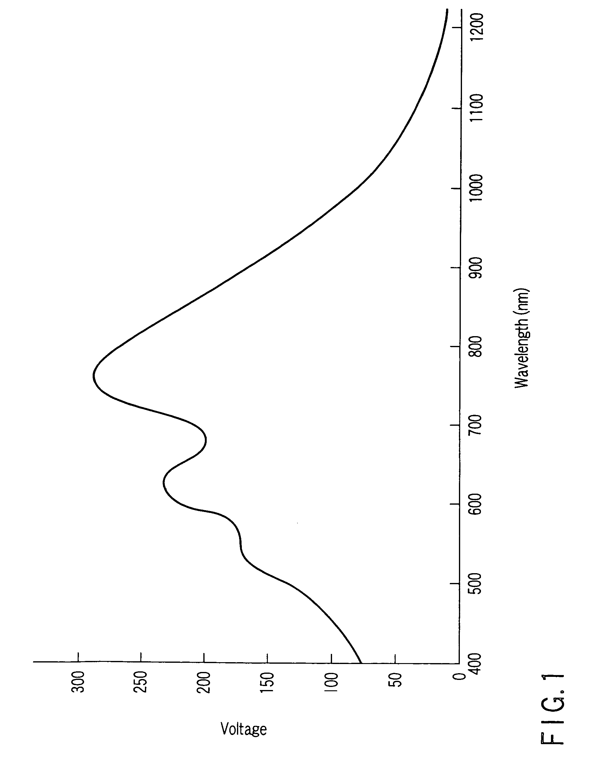
[0049]In the invention, the emission power ratio of visible light with wavelengths of 380 to 780 nm to near-infrared light with wavelengths of 750 to 1100 nm is 0.5:1 to 4.0:1. The reason why the wavelength range of the near-infrared light includes part of the visible light range (750 to 780 nm) will now be described with reference to FIG. 1.
[0050]FIG. 1 is a graph illustrating the sensitivity characteristic of a CCD camera widely used and also used as an infrared night imaging vision apparatus. As can be understood from the figure, concerning the sensitivity characteristic of the CCD camera used as the infrared night imaging vision apparatus, the camera exhibits the maximum sensitivity for light with a wavelength of about 759 nm, and exhibits lower sensitivity levels for light with wavelengths longer than 759 nm. It is evident from this that near-infrared light with wavelengths of about 780 to 1200 nm can be sensed by a near-infrared type CCD camera. Actually, however, it would be advisable to use visible light with wavelengths of 750 to 780 nm, in addition to this near-infrared light, in order to increase the emission power of light that can be sensed by the CCD camera.
[0051]Because of the above, the invention utilizes an emission range of 750 to 1100 nm for the infrared night imaging vision apparatus. On the other hand, it can also be understood from FIG. 1 that visible light with wavelengths of less than 750 nm can be utilized for the infrared night imaging vision apparatus. However, if such visible light is also utilized for the infrared night imaging vision apparatus, the energy of a visible light flux is significantly reduced. Further, for the wavelength range exceeding 1100 nm, the CCD camera exhibits an extremely low sensitivity.
[0052]If the emission power ratio is set to 0.5:1 to 4.0:1, it enables various types of use of the metal halide lamp, as will be described later. In the inventions recited in claims 1 to 3 of the present application, assume that the emission power ratio is measured in the initial stage of distribution of metal halide lamps as finished products.

Problems solved by technology

Apparatuses of this type are disadvantageous in that the camera is expensive and its accuracy of detection is degraded when it rains or snows.
This lamp unit, however, cannot be used as a vehicle headlight.
As a result, they become expensive.
Accordingly, they are liable to move through the material of a hermetic vessel when a voltage is applied.
This phenomenon raises a problem in which the energy of emission of near-infrared light is reduced during long-term lighting of a metal halide lamp.
However, a more serious problem is raised if the visible light and near-infrared light of a metal halide lamp are simultaneously utilized.
This shortens the actual life of the lamp.
Therefore, if a significant reduction in near-infrared light output occurs during long-term lighting, the visibility performance of the infrared night imaging vision apparatus itself may well disappear.

Method used


Image

  • Metal halide lamp and metal halide lamp lighting device with improved emission power maintenance ratio
  • Metal halide lamp and metal halide lamp lighting device with improved emission power maintenance ratio
  • Metal halide lamp and metal halide lamp lighting device with improved emission power maintenance ratio

Examples


example 1

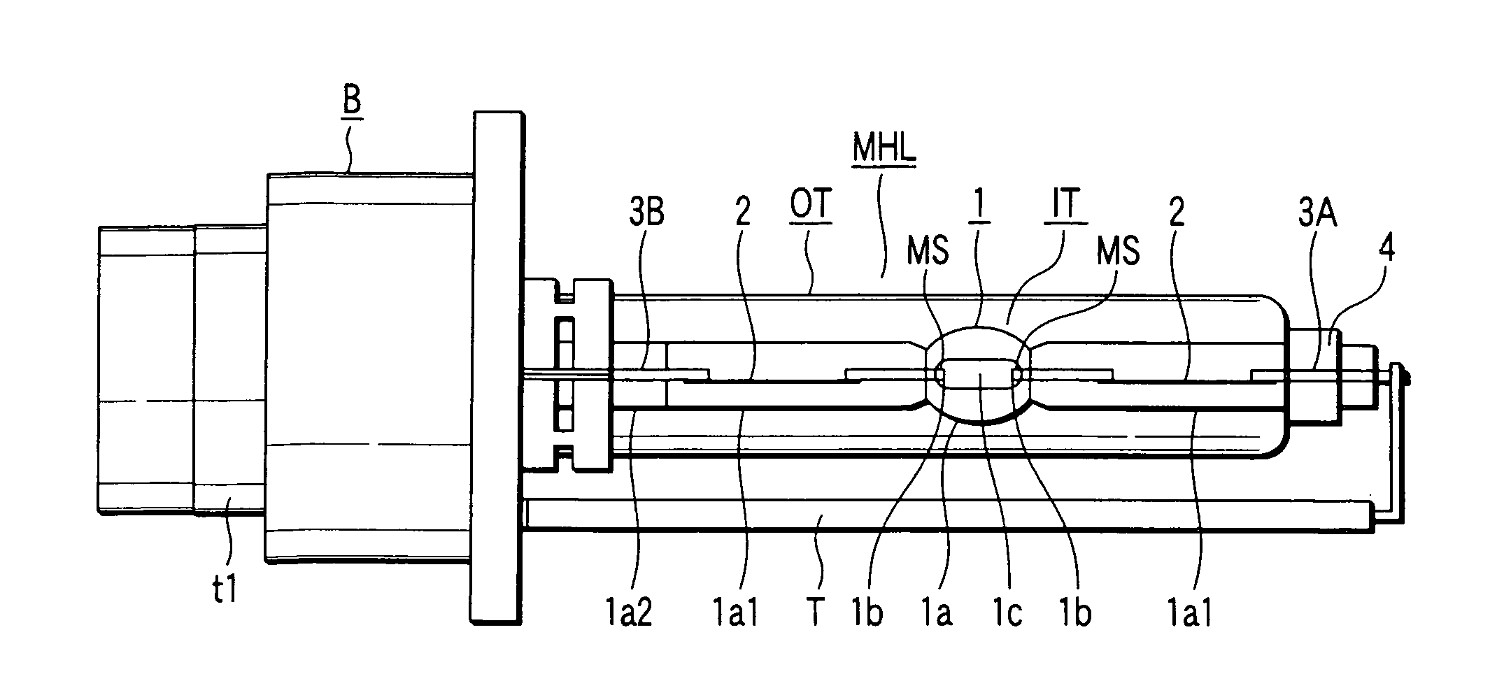
[0137]The metal halide lamp of FIG. 4 according to the first embodiment of the invention has the following specifications:

[0138]Discharge tube (light emission tube) IT[0139]Hermetic vessel 1a: Made of quartz glass; Bulb length of 7 mm; Maximum outer diameter of 6 mm; Entire length of 50 mm; Maximum inner diameter of 2.6 mm; Internal volume of 0.025 cc.[0140]Metal storing means MS: Formed of the portion of each electrode projecting into the hermetic vessel; Formed of a tungsten wire mainly doped with 66 ppm of potassium (concerning the doped components, see Table 1)[0141]Electrode 1b: Formed of a doped tungsten wire with a diameter of 0.35 mm; Inter-electrode distance of 4.2 mm; Projection length of 1.3 mm[0142]Discharge Medium[0143]First halide: 0.26 mg of NaI; 0.13 mg of ScI3 [0144]Second halide: 0.04 mg of RbI[0145]Third halide: 0.2 mg of ZnI2 [0146]Rare gas: 10 atoms of xenon (Xe)[0147]Outer tube OT: Outer diameter of 9 mm; Inner diameter of 7 mm; Internal pressure=atmospheric pr...

example 2

[0164]A metal halide lamp according to example 2 of the first embodiment of the invention has specifications below, the other specifications being similar to those of example 1.[0165]Electrode 1b: Formed of a doped tungsten wire with a diameter of 0.38 mm[0166]Discharge medium[0167]First halide: 0.5 mg of NaI; 0.1 mg of ScI3 [0168]Second halide: 0.4 mg of CsI[0169]Third halide: 0.2 mg of ZnI2 [0170]Rated lamp power: 40 W[0171]Emission power ratio (during stable lighting):[0172]Visible light (380 to 780 nm) / near-infrared light (750 to 1100 nm)=0.82

[0173]In the following Table 3, only the electrode material is varied between the shown metal halide lamps, and the other specifications of the shown lamps are similar to those of example 2. Specifically, Table 3 shows the types of doped components, the luminous flux maintenance ratio 3000 hours after lighting (the ratio of the total luminous flux 3000 hours after lighting to that of the initial time), and the near-infrared emission power m...


PUM


Abstract

A metal halide lamp includes a refractory, light-transmitting hermetic vessel, a pair of electrodes sealed in thehermetic vessel, a discharge medium including a halide and a rare gas, and metal storing means storing at least one selected from the group consisting of potassium (K), rubidium (Rb) and cesium (Cs), the metal storing means being heated during lighting and gradually discharging at least one metal in the hermetic vessel.

Description

CROSS-REFERENCE TO RELATED APPLICATIONS[0001]This application is based upon and claims the benefit of priority from prior Japanese Patent Application No. 2003-424941, filed Dec. 22, 2003, the entire contents of which are incorporated herein by reference.BACKGROUND OF THE INVENTION[0002]1. Field of the Invention[0003]The present invention relates to a metal halide lamp suitable as a light source for a vehicle headlight and / or infrared night imaging vision apparatus, and a metal halide lamp lighting apparatus using the metal halide lamp.[0004]2. Description of the Related Art[0005]Various researches have been made concerning the safety of vehicles. See, for example, “Illuminating Engineering Institute Journal”, Vol. 86, No. 12, pp. 896-899, published 2002. This document discloses an infrared night imaging vision apparatus for vehicles as vehicle safety means. Infrared night imaging vision apparatuses for vehicles are called “Night Vision” (trademark), and developed as nighttime safety...

Claims


Application Information

Patent Timeline
Patent Type & Authority Patents(United States)
IPC IPC(8): H01J61/12H01J17/20H01J61/18F21S8/10F21Y101/00H01J61/073H01J61/20H01J61/22H01J61/28H01J61/82H01J61/88
CPCF21S48/1186H01J61/125H01J61/22H01J61/28H01J61/34H01J61/827F21S41/172
Inventor ISHIGAMI, TOSHIHIKOMATSUDA, MIKIOHIRUTA, TOSHIO
Owner HARISON TOSHIBA LIGHTING CORP
Why Eureka
Try Eureka