
Lighting controller for lighting device for vehicle

a technology for lighting devices and controllers, applied in the direction of electric variable regulation, process and machine control, instruments, etc., can solve the problems of led failure, led failure, and power loss increase, and achieve the effect of suppressing power loss

Active Publication Date: 2008-04-01
KOITO MFG CO LTD
View PDF2 Cites 30 Cited by
  • Summary
  • Abstract
  • Description
  • Claims
  • Application Information

AI Technical Summary

Benefits of technology

The present invention relates to a lighting controller for a vehicle that can suppress a current supplied to a semiconductor light source during a transient time and prevent power loss during a steady state. The controller includes a current supply control unit, a current detecting unit, a resistance element, a switch unit, and a switch control unit. The current detecting unit detects the current supplied to the semiconductor light source and sends the information to the switch control unit. The switch control unit decides whether the current is a current showing a transient state or a steady state. If the current is transient, the switch unit turns off to restrain the over-current from being supplied to the semiconductor light source. If the current is steady, the switch unit turns on to supply the current without consuming the resistance element and prevent power loss. The switch control unit also determines the time required for the current to reach a steady state and delays the switch unit's turning on or off accordingly to ensure the proper functioning of the controller.

Problems solved by technology

However, during a transient time, for instance, at the time of starting by turning on a power switch, when the lighting control circuit performs a control for allowing a supply current to the LED to come close to a set value, if a control delay arises, the supply current to the LED exceeds the set value to overshoot so that an over-current may be supplied to the LED.
When the over-current is supplied to the LED, a bonding wire is disconnected or a chip is deteriorated due to a current concentration.
Thus, the LED fails.
However, in this method, because the current is consumed by the resistance element even in a steady state, a power loss is increased.

Method used


Image

  • Lighting controller for lighting device for vehicle
  • Lighting controller for lighting device for vehicle
  • Lighting controller for lighting device for vehicle

Examples


Embodiment Construction

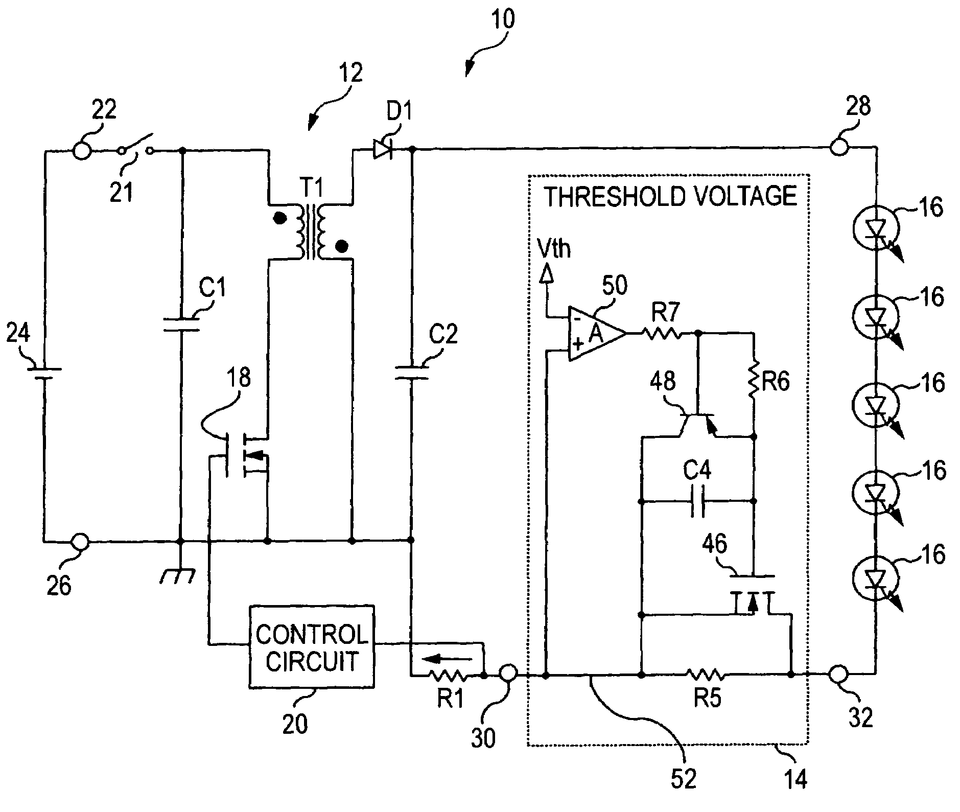
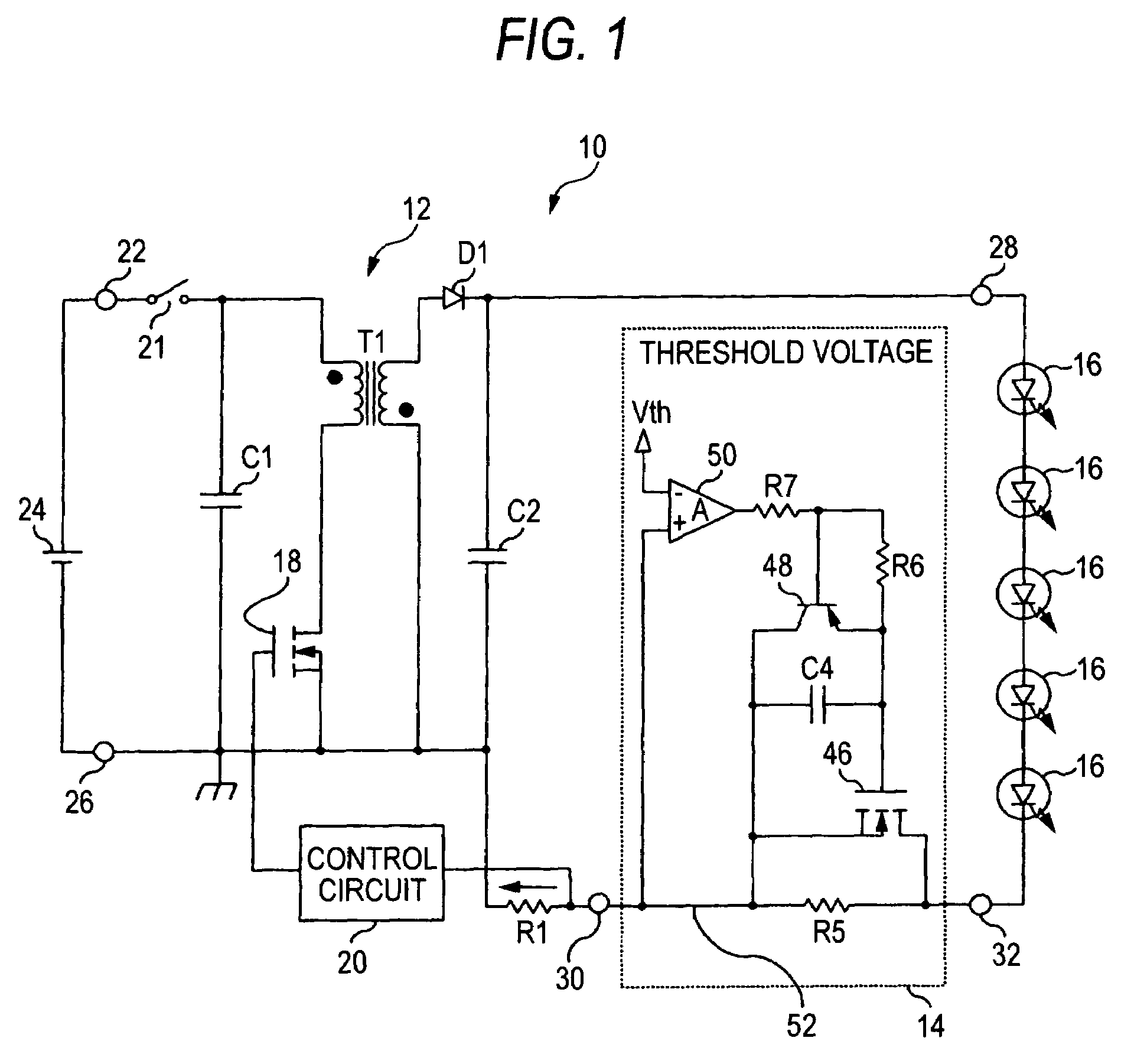
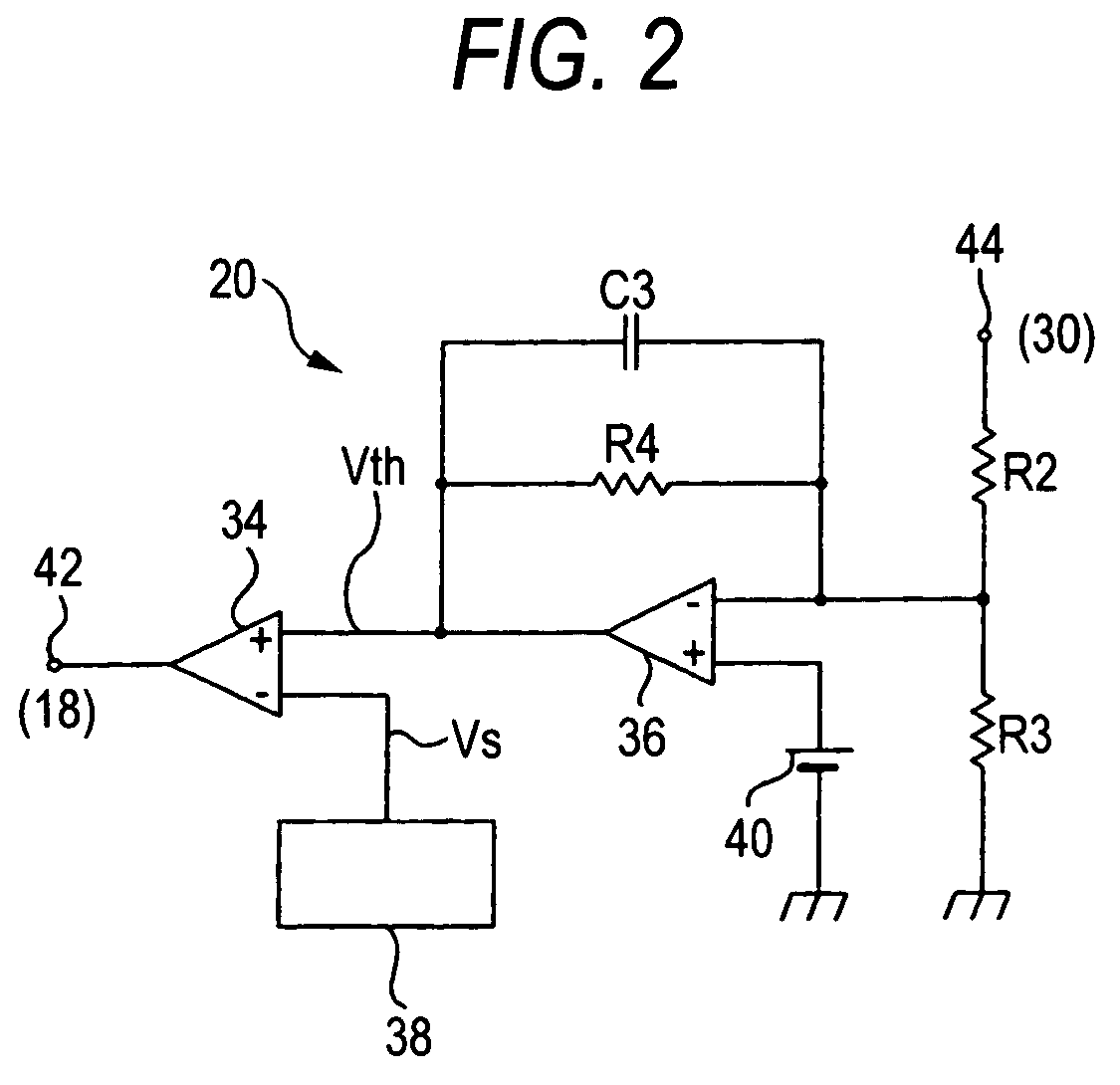
[0033]Now, embodiments of the present invention will be described below by referring to the drawings. FIG. 1 is a circuit block diagram of a lighting controller for a lighting device for a vehicle showing a first embodiment of the present invention. FIG. 2 is a circuit block diagram of a control circuit. FIG. 3 is a wave form diagram for explaining the operation of the control circuit. FIG. 4 is a circuit diagram showing a connecting relation between a contactor and an LED. FIG. 5 is a diagram for explaining a setting method of a constant of a resistance element. FIG. 6 is a circuit block diagram of a lighting controller for a lighting device for a vehicle showing a second embodiment of the present invention.

[0034]In these drawings, a lighting controller for a lighting device for a vehicle includes, as shown in FIG. 1, a constant current control type switching regulator 12 and a protecting circuit 14 as elements of the lighting device (a light emitting device) for a vehicle. To the ...


PUM


Abstract

A lighting controller for a lighting device for a vehicle includes a semiconductor light source; a power source for supplying electric power; and control circuitry for controlling a supply of a current to the semiconductor light source. The control circuitry selectively supplies the current to the semiconductor light source through a resistance element or through a bypass circuit for bypassing the resistance element based on a determination of a state of the current. A method for controlling a lighting device for a vehicle includes receiving electric power from a power source; supplying a current to a semiconductor light source; determining a state of the current supplied to the semiconductor light source; and selectively supplying the current to the semiconductor light source through a resistance element or through a bypass circuit for bypassing the resistance element based on the determination of the state of the current.

Description

BACKGROUND OF INVENTION[0001]1. Field of the Invention[0002]The present invention relates to a lighting controller for a lighting device for a vehicle, and more particularly to a lighting controller for a lighting device for a vehicle constructed so as to control a semiconductor light source composed of a semiconductor light emitting element to be turned on.[0003]2. Background Art[0004]As the lighting device for a vehicle, a lighting device for a vehicle using a semiconductor light emitting element such as an LED (Light Emitting Diode) as a light source has been known. Mounted on such a lighting device for a vehicle is a lighting control circuit for controlling the LED to be turned on.[0005]As the lighting control circuit, for instance, a lighting control circuit has been proposed in which the battery voltage of a vehicle is boosted and the boosted voltage is applied to LEDs to drive a light source having a plurality of LEDs connected in series (see Patent Document 1).[0006]In such ...

Claims


Application Information

Patent Timeline
Patent Type & Authority Patents(United States)
IPC IPC(8): H05B41/16H05B44/00B60Q11/00H01L33/00
CPCH05B33/0815H05B33/089H05B45/50H05B45/382H05B45/385
Inventor SHIOTSU, FUMINORIITO, MASAYASU
Owner KOITO MFG CO LTD
Learn More