Crystal oscillation circuit

a crystal oscillation circuit and crystal oscillation technology, applied in the field of crystal oscillation circuits, can solve the problems of insufficient suppression of b mode, inability to positively suppress the oscillation of b mode using a coil and a capacitor, and the operation of oscillation is performed, so as to reduce the required cost, improve productivity, and simplify the effect of adjustmen

Inactive Publication Date: 2008-04-01
NIHON DEMPA KOGYO CO LTD
View PDF6 Cites 6 Cited by
  • Summary
  • Abstract
  • Description
  • Claims
  • Application Information

AI Technical Summary

Benefits of technology

[0027]Using resistance for an unnecessary mode, a crystal oscillator can be downsized, and a simpler adjustment can be made. In addition, since a general-purpose part having a no large Q value can be used, the productivity can be improved and the required cost can be reduced.

Problems solved by technology

Therefore, when an oscillator is actually produced, there can be the problem that the oscillation is performed in the B mode as the secondary oscillation.
However, a circuit using a coil and a capacitor cannot positively suppress the oscillation in the B mode.
Therefore, the B mode cannot be sufficiently suppressed.
That is, there is the problem that the negative resistance at the frequency of the B mode in an oscillation circuit remains as the negative state.
In the method described in the above-mentioned patent document, it is not possible to make the negative resistance of the frequency in the B mode a positive value.
However, as shown in FIG. 2, it is difficult to correctly make an adjustment because a positive value can be obtained only in a narrow bandwidth in the B mode (for example, 10.9 MHz).
In addition, since a quartz oscillator is used, it is costly.
Therefore, it is difficult to stably apply it in a wide temperature range.
When a coil having a large Q value and a capacitor are used, it is hard to make an adjustment because the pass band width in the C mode is very narrow.
When a ceramic resonator is used, it is hard to make an adjustment because there is much spurious of the ceramic resonator itself.

Method used


Image

  • Crystal oscillation circuit
  • Crystal oscillation circuit
  • Crystal oscillation circuit

Examples


Embodiment Construction

[0035]The details of the modes for embodying the present invention are explained below by referring to the attached drawings.

(Example of Circuit Configuration)

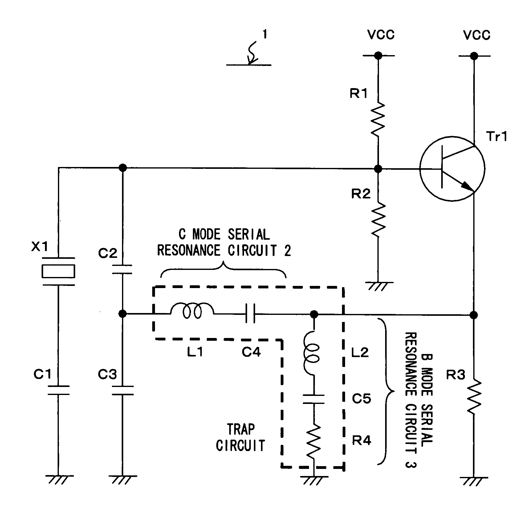
[0036]FIG. 3 shows an example of the crystal oscillation circuit according to the present invention. X1 shown in FIG. 3 is a quartz oscillator in which a C mode (main mode) frequency of an SC cut, an IT cut, etc. is close to a B mode (unnecessary mode) in the crystal cutting method.

[0037]One terminal of the quartz oscillator X1 is connected to a capacitance device C1, and the other terminal is connected to the base terminal of an amplifier (transistor amplifier) Tr1. Furthermore, the base terminal of the Tr1 is connected to one terminal of the resistance devices R1 and R2 and one terminal of a capacitance device C2.

[0038]Next, the emitter terminal of the amplifier Tr1 is connected to one terminal of the resistance device R3, the main mode resonance circuit, and the trap circuit.

[0039]The main mode resonance circuit is constitu...


PUM


Abstract

A crystal oscillation circuit can correctly suppress the resonance of a B mode, thereby correctly excite the resonance of a C mode. Since the crystal oscillation circuit uses a quartz oscillator of an SC cut or an IC cut, the B mode (unnecessary mode) frequency is close to the C mode (main mode) frequency. Therefore, a C mode resonance circuit (main mode resonance circuit) for passing a C mode frequency and a trap circuit for suppressing the oscillation at an unnecessary mode frequency are provided in the feedback loop of the crystal oscillation circuit.

Description

[0001]This application claims priority under 35 U.S.C. 119 to Japanese Application No. 2005-167531, filed Jun. 7, 2005, which application is incorporated herein by reference and made a part hereof.BACKGROUND OF THE INVENTION[0002]1. Field of the Invention[0003]The present invention relates to a crystal oscillation circuit, and more specifically to a technology of suppressing the unnecessary oscillation of a quartz oscillator.[0004]2. Description of the Prior Art[0005]Generally, a piezoelectric crystal used for a quartz oscillator can excite the piezoelectric oscillation only at a specific cutting angle for a crystallographic axis. SC-cut and IT cut quartz oscillators are well known as quartz oscillators appropriate for such an oscillator.[0006]However, the SC-cut and II-cut quartz oscillators generate B mode and A mode secondary oscillation (unnecessary mode) near the resonance in the C mode (main mode) as primary oscillation, and at the high frequency side.[0007]Since the value of ...

Claims


Application Information

Patent Timeline
Patent Type & Authority Patents(United States)
IPC IPC(8): H03B5/32
CPCH03B5/32H03B5/36
Inventor OITA, TAKEO
Owner NIHON DEMPA KOGYO CO LTD
Why Eureka
Try Eureka