Waveguide adapter for probe assembly having a detachable bias tee

a waveguide adapter and probe technology, applied in the field of high-frequency probe assemblies with bias tees, can solve the problems of significant signal degradation, difficult to adjust the transition, and particular probe and waveguide assemblies are not designed to be used repeatedly

Inactive Publication Date: 2008-04-01
CASCADE MICROTECH
View PDF9 Cites 4 Cited by
  • Summary
  • Abstract
  • Description
  • Claims
  • Application Information

AI Technical Summary

Benefits of technology

[0012]The following presents a simplified summary of the disclosed system, apparatus or method in order to provide a basic understanding of some of its aspects. This summary is not an extensive overview and is intended to neither identify key or critical elements or delineate a scope of the disclosed system, apparatus or method. The sole purpose of this summary is to present some concepts in simplified form as a prelude to the more detailed description that is presented later.

Problems solved by technology

Tuning of the transition is often difficult.
At high frequencies, very small deviations from an optimal backshort position may lead to significant signal degradation.
Unlike measurement equipment, however, a particular probe and waveguide assembly is not designed to be used repeatedly on successive types of DUTs, especially with different frequency ranges.
Also, probes are contacting elements and eventually wear out after a number of uses.
Because of the aforementioned requisite manual tuning and precise positioning of the backshort, repetitive construction and tuning of bias tees is time consuming.

Method used


Image

  • Waveguide adapter for probe assembly having a detachable bias tee
  • Waveguide adapter for probe assembly having a detachable bias tee
  • Waveguide adapter for probe assembly having a detachable bias tee

Examples


Embodiment Construction

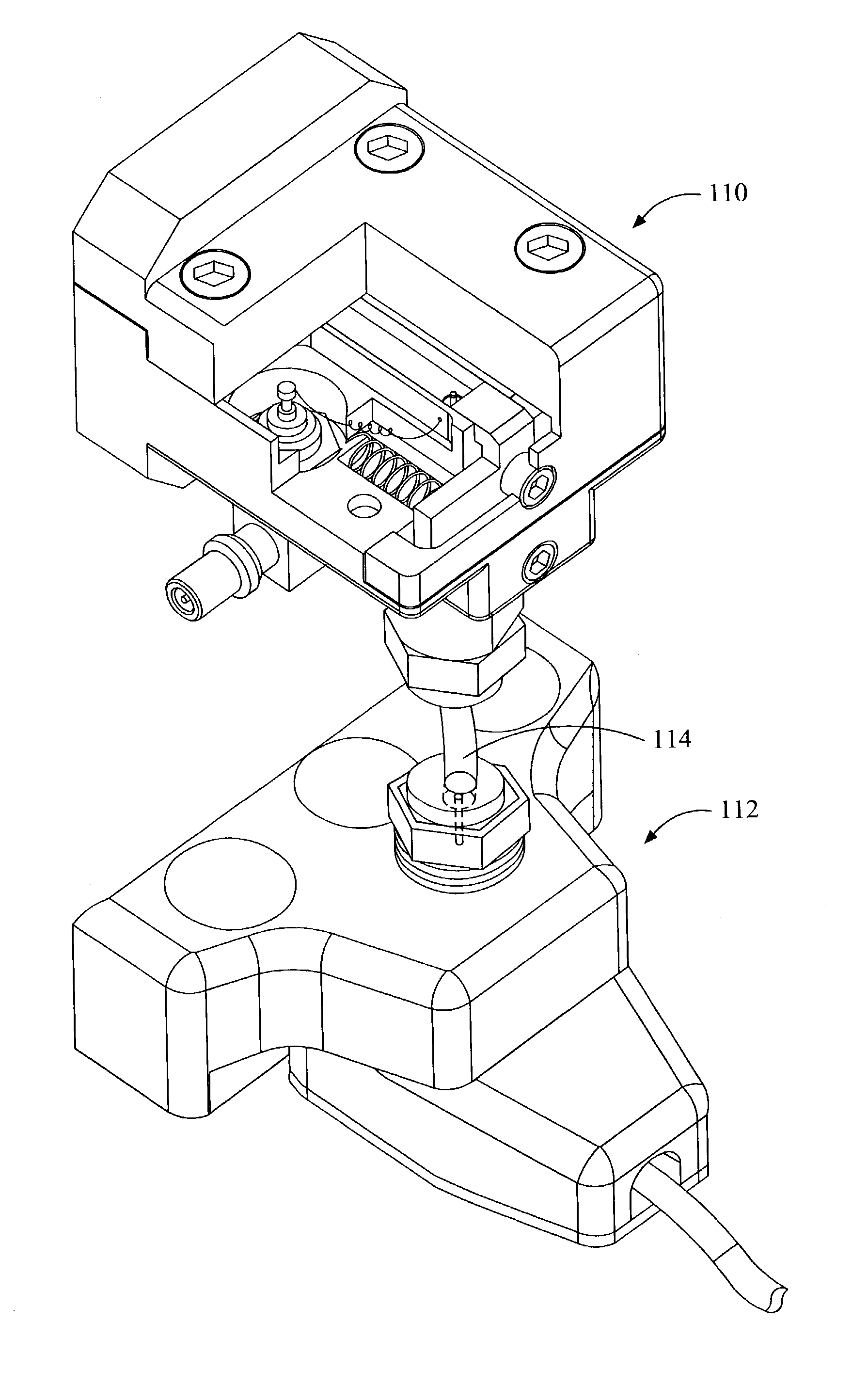
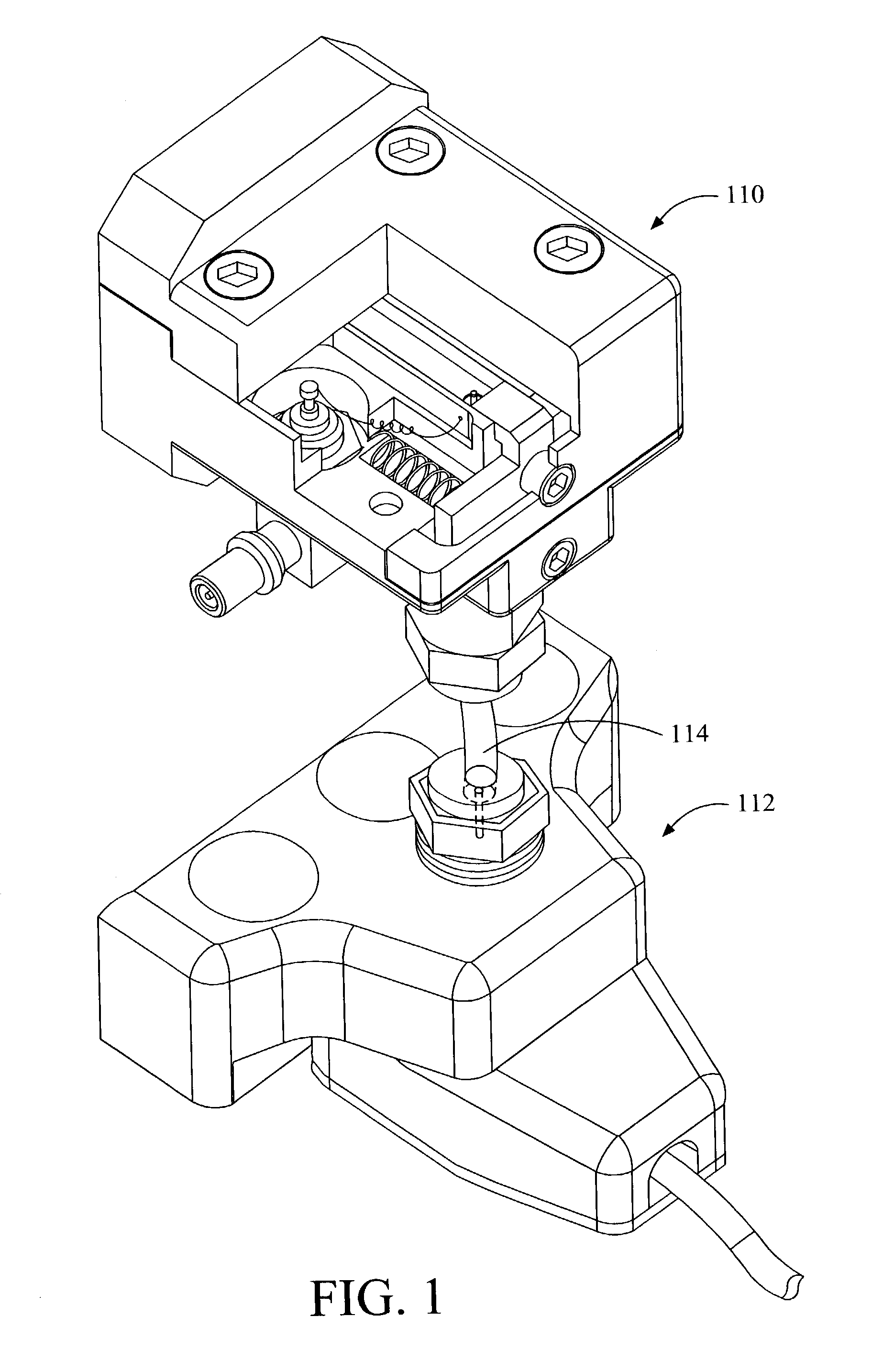
[0021]Referring to FIG. 1, one embodiment of a probe assembly comprises a bias tee and a transition 110 detachably connected to a probe 112 through a coaxial cable 114. It is to be understood that the probe assembly may include any probe, any transition, and any bias tee. Also, other connectors and transition paths may be used to provide a detachable interconnection between the transition bias tee 110 and the probe 112, together with the passage of a signal from the transition bias tee 110 to the probe 112.

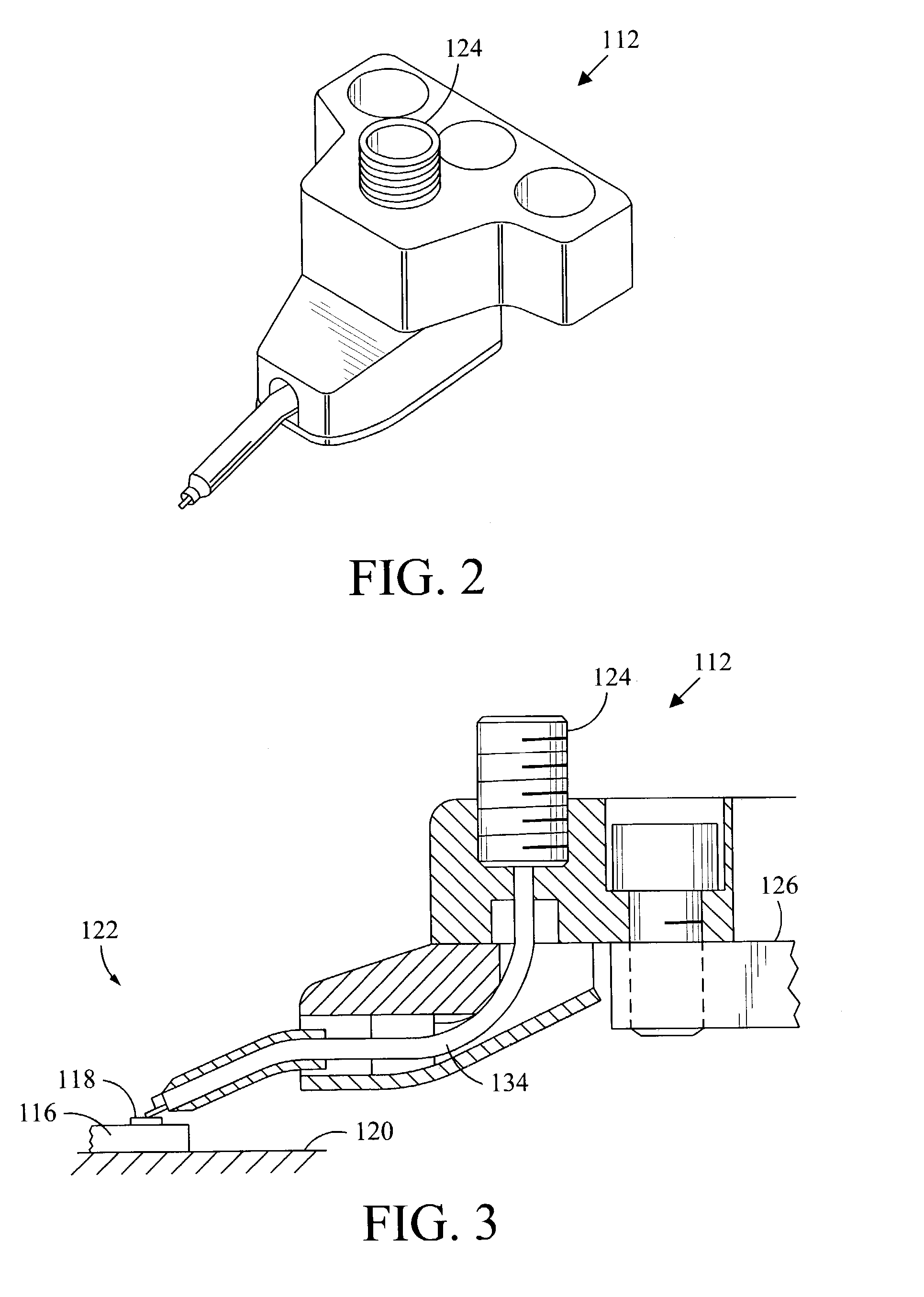
[0022]FIG. 2 shows an exemplary probe 112 that may be used. Referring also to FIG. 3, the probe 112 is designed to be mounted on a probe-supporting member 126 of a wafer probe station so as to be in a suitable position for probing a DUT, such as an individual component or pad on a wafer 116. In this type of application, the wafer is typically supported under vacuum pressure on the upper surface of a chuck 120.

[0023]Ordinarily, an x-y-z positioning mechanism such as a micrometer kn...


PUM


Abstract

A probe assembly including a probe, a waveguide to transmission path transition, and a bias tee detachably connected to the probe.

Description

[0001]This application claims the benefit of the U.S. Provisional Patent Application Ser. No. 60 / 368,829 filed Mar. 28, 2002.BACKGROUND OF THE INVENTION[0002]The present invention relates to a probe assembly for testing electrical devices such as silicon wafers, and more particularly to a high-frequency probe assembly having a bias tee.[0003]High frequency testing of an electrical device-under-test (DUT) is usually accomplished by electrically connecting measurement equipment to a high frequency probe assembly that selectively probes contact points on the DUT. Existing probe assemblies include, for example, needle probes, and microwave probes.[0004]Some measurement equipment is designed to be used repeatedly over time in conjunction with different types of probe assemblies. The measurement equipment, therefore, includes input and output ports for connectivity to the probe assembly. Because coaxial adapters have only recently been able to efficiently deliver signals above 65 GHz, fre...

Claims


Application Information

Patent Timeline
Patent Type & Authority Patents(United States)
IPC IPC(8): H01P5/103
CPCH01P5/103
Inventor ANDREWS, MIKEHAYDEN, LEONARDMARTIN, JOHN
Owner CASCADE MICROTECH
Why Eureka
Try Eureka