Method and apparatus for automatic load testing using bi-directional testing

a technology of automatic load testing and bi-directional testing, which is applied in the direction of mechanical measurement arrangements, instruments, and mechanical means, etc., can solve the problems of high cost of static load testing, significant danger to operating personnel, and inability to work alone for a single operator

Active Publication Date: 2008-04-08
HEWLETT PACKARD DEV CO LP +1
View PDF11 Cites 22 Cited by
  • Summary
  • Abstract
  • Description
  • Claims
  • Application Information

AI Technical Summary

Benefits of technology

[0025]By providing computer control of the load testing procedure, together with automatic data logging, the present invention can provide a much more detailed analysis of the structural integrity of each section of the pile to be obtained. This analysis can be presented in real-time, advantageously in tabulated and / or graphic form, and reduces the risk of errors being introduced through manual processing of the data.
[0033]Accordingly, an alternative embodiment uses one or more electronic load cells. In a further embodiment, the electronic load cells can employ balanced strain gauges around a coaxial element. These may be placed above the jack on, for example, a spherical seating arrangement so as to reduce the risk of eccentric loading. Because the load cells measure the actual load applied to the pile elements, it is possible to operate the jack or jacks at the same level by way of the hydraulic control system so as to apply a substantially constant load, even when the pile elements are undergoing displacement. This feedback mechanism allows the applied load to each element to be held constant to a degree hitherto not achieved with manually-operated systems. The time interval between successive measurements of applied load and pile element displacement can be of the order of a few seconds, for example from 1 to 5 seconds. With the hydraulic control system set to adjust the hydraulic pressure applied to the jack or jacks in direct response to these measurements and on a similar timescale, a level of control previously not attained can be achieved, thereby greatly improving the quality of the testing results.
[0034]Advantageously, the computer can be arranged to prolong the duration of application of load until the specified settlement rate has been achieved. In addition, the computer can be arranged so as to halt the testing process automatically, by for example, stopping the flow of hydraulic fluid to the jack or jacks, when certain conditions are detected. This automatic fail-safe procedure is a further advantage over the known methods of static load-testing, and can allow the present invention to be left unattended without undue risk. The fail-safe condition may be triggered, for example, in one or more of the following situations:
[0040]vi) In embodiments of the present invention in which two or more displacement sensors are disposed at different locations about the circumference of the pile element, where the difference between the magnitudes of the displacements measured by the two or more displacement sensors reaches or exceeds a predetermined value, for example 50% of the average value recorded. This indicates that unwanted lateral loads are being applied to the pile, which in extreme cases can lead to premature structural damage or failure. This fail-safe also helps to detect misreading from one or more of the displacement sensors.

Problems solved by technology

Because the applied test loads tend to be high, there is a significant danger to operating personnel should the cross-beam or its anchorages fail, particularly if the operating personnel are required to read test values from one or more gauges located on equipment located close to the top of the pile.
Furthermore, because the applied test load has to be maintained and adjusted by operating the jack manually, it is necessary for operating personnel to be in attendance at all times. It is not safe for a single operator to work alone, particularly overnight (the typical time taken to perform a comprehensive static load test can often be as much as 18 hours).
Accordingly, the typical method of static load testing is expensive, as well as being slow.
Another disadvantage of the known static load-testing equipment is that the quality of the data obtained is not always consistently good.
Although manual reading and recording of the dial gauges employed in a static load test should not present an insurmountable difficulty in terms of accuracy and regularity, it is the application of the load that generally is the source of poor quality data.
A further source of error arises through the use of a pressure gauge to derive the applied test load by way of calibration charts.

Method used


Image

  • Method and apparatus for automatic load testing using bi-directional testing
  • Method and apparatus for automatic load testing using bi-directional testing
  • Method and apparatus for automatic load testing using bi-directional testing

Examples


Embodiment Construction

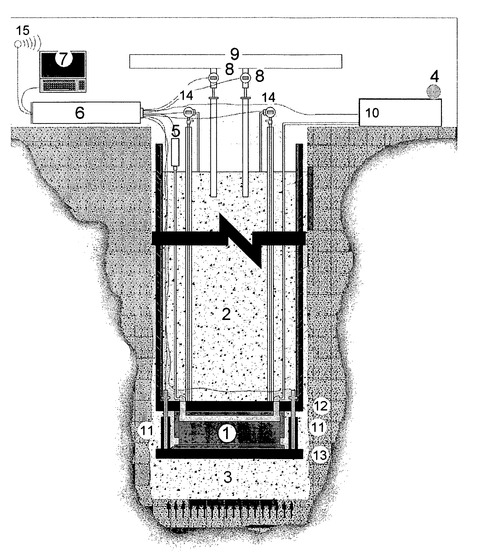
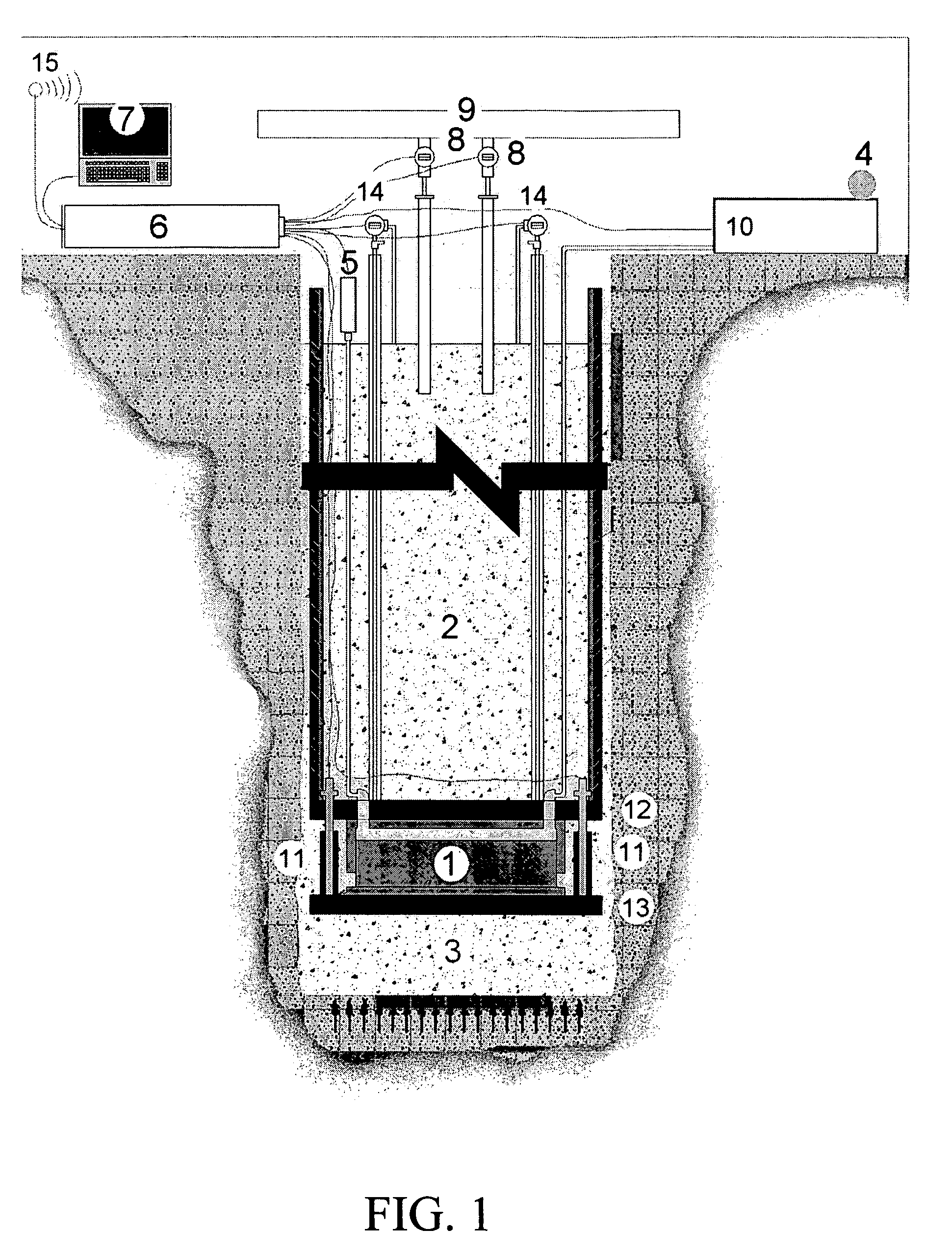
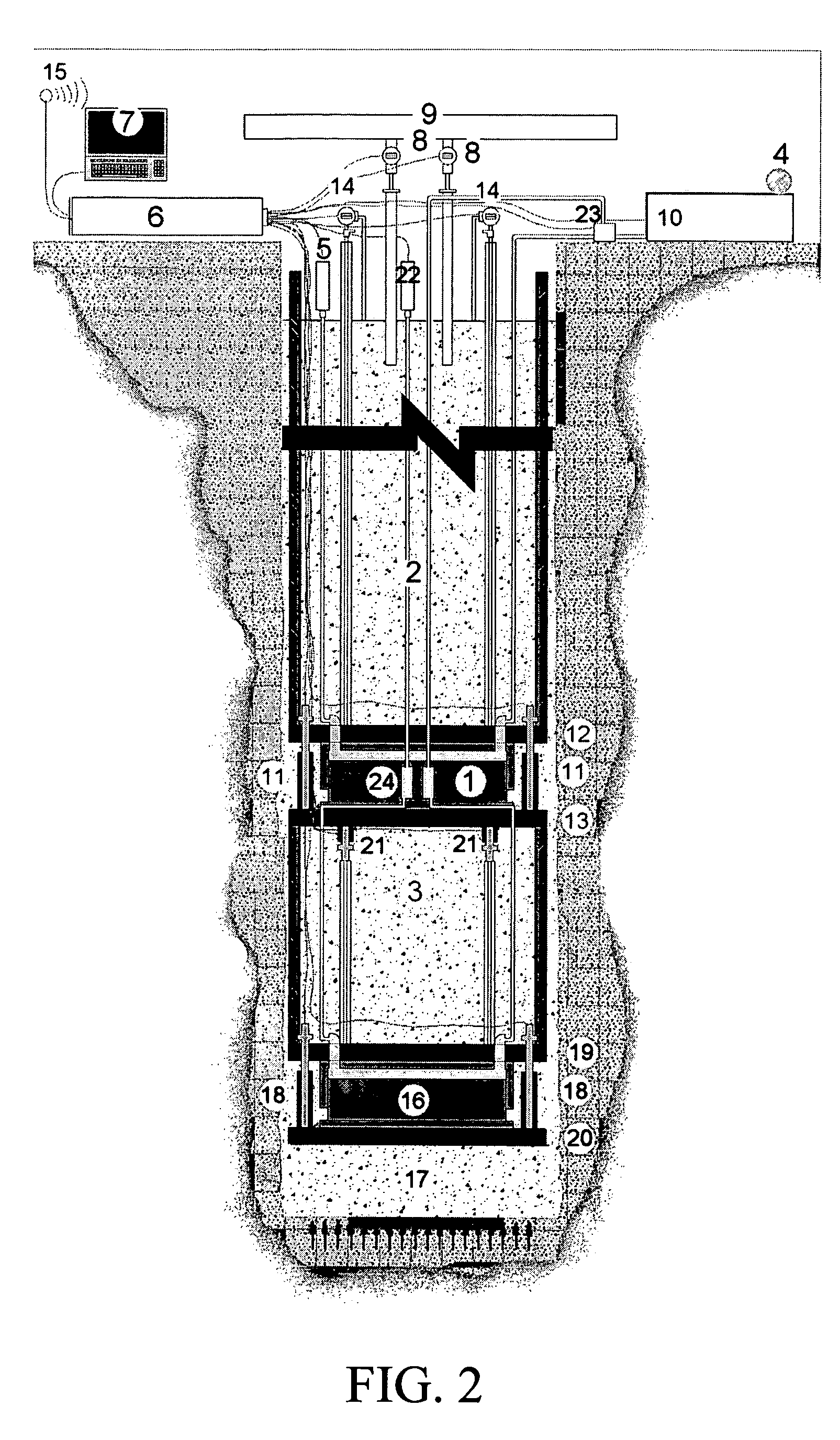
[0051]The subject invention pertains to a method and apparatus for automatic load testing of a foundation element using bi-directional testing. The subject invention can be applicable to any foundation element in the ground to support structural loads, such as a diaphragm wall, berrettes, or a pile as described in the embodiments of the subject invention. The subject invention can incorporate a means to apply a test load to a pile. In a specific embodiment, the means to apply a test load can incorporate a load device. In an embodiment of the subject invention, a load device is located between two sections of a pile such that the pile is split into a first pile element above the load device and a second pile element below the load device. The pile can be, for example, bored cast in-situ concrete, driven precast concrete, or driven steel tubular piles. For the steel tubular piles, steel tubes can be driven or pushed into the ground, concrete can be poured in, and then the steel tubes ...


PUM

PropertyMeasurementUnit
timeaaaaaaaaaa
displacementaaaaaaaaaa
timeaaaaaaaaaa

Abstract

The subject invention pertains to a method and apparatus for testing the static load-bearing capacity of a pile. In an embodiment, one or more load devices for applying a test load can be disposed within a pile such that a pile element can be above the load device, and a pile element can be below the load device. Upon applying a test load, the pile element above the load device and the pile element below the load device tend to separate. The test loads applied to the pile can be controlled in response to the magnitude of the test load, the combined settlement rate of the pile elements, the displacement of the pile elements, and the compression of the pile elements. A test regime can continue until a programmed regime is completed or a fail-safe trigger event occurs.

Description

CROSS-REFERENCE TO RELATED APPLICATION[0001]This application claims priority from provisional application U.S. Ser. No. 60 / 592,484; filed Jul. 30, 2004, which is hereby incorporated by reference herein in its entirety, including any figures or drawings.FIELD OF THE INVENTION[0002]The present invention relates to a method and apparatus for testing the static load-bearing capacity of engineering piles.BACKGROUND OF INVENTION[0003]Piles, usually made out of concrete, are generally used to form the foundations of buildings or other large structures. Before using the piles as a foundation for further building work, it is important to test the static load-bearing capacity of each pile. This is generally done by applying a test load to the top of a pile by way of a hydraulic jack braced against a reaction system having a cross-beam that is anchored in place at its ends. The test load is generally measured by monitoring the hydraulic pressure supplied to the jack, and the associated displac...

Claims


Application Information

Patent Timeline
Patent Type & Authority Patents(United States)
IPC IPC(8): G01B5/00G01B7/16G01L1/00G01N3/00G01N33/24
CPCE02D33/00G01N3/00G01N3/02
Inventor ENGLAND, MELVIN G.HAYES, JOHN A.
Owner HEWLETT PACKARD DEV CO LP
Why Eureka
Try Eureka