Oil ring

a technology of oil rings and rings, applied in the field of oil rings, can solve problems such as complicated work operations, and achieve the effects of reducing sliding friction and preventing excessive pressure from concentrating

Inactive Publication Date: 2008-04-08
NIPPON PISTONRING CO LTD +1
View PDF18 Cites 22 Cited by
  • Summary
  • Abstract
  • Description
  • Claims
  • Application Information

AI Technical Summary

Benefits of technology

[0011]The present invention has been accomplished in view of the above problem, and a main object is to provide an oil ring which is capable of reducing the sliding friction even in a high speed revolution region of the piston, which has excellent oil consumption and which can easily be worked.
[0013]In the present invention, by forming the sliding projection into the above described shape, when the oil ring is adversely inclined and obliquely contacts against the cylinder inner wall, the outer edge portion which comes into contact with the cylinder inner wall can be contacted at its curved surface. Therefore, it is possible to prevent concentration of excessive pressure at the outer edge portion, and to reduce the sliding friction.
[0015]In the present invention, like the above mentioned invention, the sliding friction can be reduced by providing the sliding surface with the curved surface sliding portion. Further, in the outer side surface of sliding projection, a portion with a curved surface is formed on at least a part from the outer edge portion. With this configuration, the outer edge portion can be formed into more gently curved surface. Therefore, when the oil ring is adversely inclined and obliquely contacts against the cylinder inner wall, it is possible to prevent excessive pressure applied at the outer edge portion, and thus, an effect of reducing the sliding friction can be obtained by this as well.
[0016]In the above mentioned invention, it is preferable that the curved surface sliding portion and the inner side surface of sliding projection are joined to each other. By forming the entire sliding surface into the curved surface sliding portion, the sliding surface always comes into contact with the cylinder inner wall at its curved surface and thus, the compliance to the cylinder inner wall is excellent, and the sliding friction can be reduced.
[0018]When the width is in the above mentioned range, the sliding friction can be reduced without deteriorating the scraping-off function of lubricating oil and the oil control function of the oil ring.

Problems solved by technology

However, this oil ring has a problem that it is necessary to form the upper and lower tapers such that they become different from each other and to judge the direction when the oil ring is assembled, and the work operation becomes complicated.

Method used


Image

  • Oil ring
  • Oil ring
  • Oil ring

Examples


first embodiment

A. First Embodiment

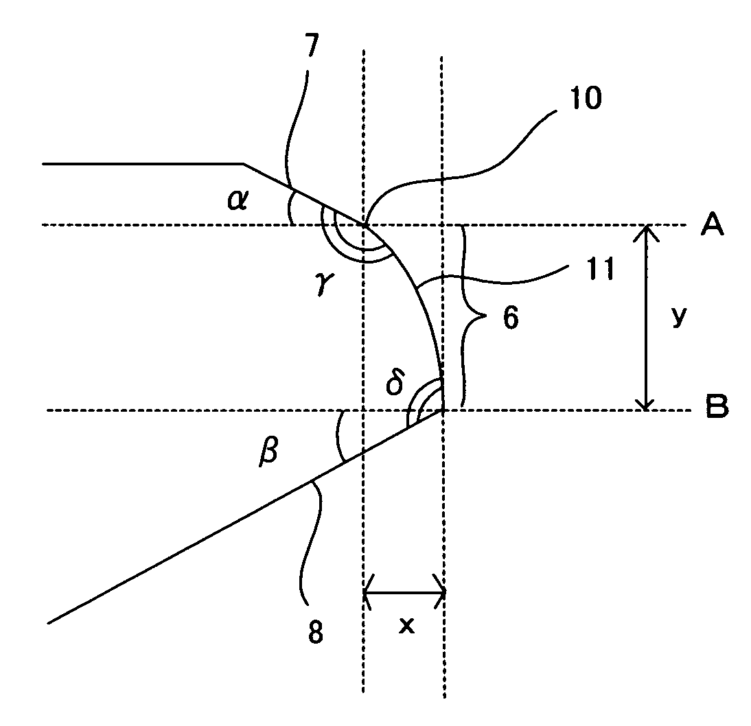
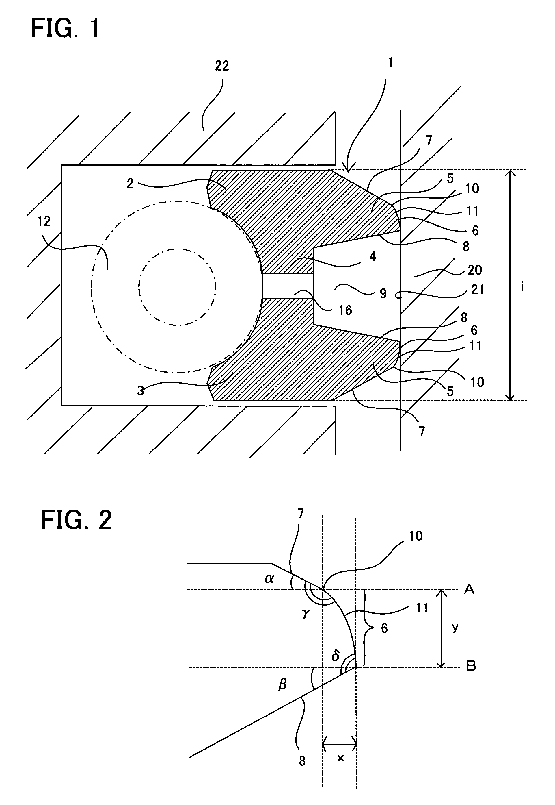
[0033]In the first embodiment, the oil ring is an oil ring which is formed into cross-section substantially of an I-shape that two rails are connected at a columnar portion thereof, wherein a sliding projection formed in each of the two rails comprises an outer side surface of sliding projection which forms an outer portion of the sliding projection, a inner side surface of sliding projection which forms an inner portion of the sliding projection, and a sliding surface which slides on a cylinder inner wall and forms a tip end of the sliding projection; wherein a taper angle of the outer side surface of sliding projection is in a range of 10° to 60°; and wherein an outer edge portion, where the outer side surface of sliding projection and the sliding surface are joined to each other, is formed into a curved surface, and the sliding surface has a curved surface sliding portion which is joined to the outer side surface of sliding projection and formed into a gently c...

second embodiment

B. Second Embodiment

[0074]Next, the second embodiment will be explained. In the present embodiment, an oil ring is formed into cross-section substantially of an I-shape that two rails are connected at a columnar portion thereof, wherein a sliding projection formed in each of the two rails comprises an outer side surface of sliding projection which forms an outer portion of the sliding projection, a inner side surface of sliding projection which forms an inner portion of the sliding projection, and a sliding surface which slides on a cylinder inner wall and forms a tip end of the sliding projection; wherein the at least a portion from an outer edge portion, where the outer side surface of sliding projection and the sliding surface are joined to each other, of the outer side surface of sliding projection is formed into a curved surface; and wherein the outer edge portion is formed into a curved surface, and the sliding surface has a curved surface sliding portion which is joined to th...

examples

[0080]The present invention will be further explained below referring to an example.

[Unit Test]

[0081]First, concerning the oil ring of the present invention, a mechanical loss (FMEP) caused by friction was obtained using a unit tester. A test method in this case is as follows. The oil ring was set in a piston, running-in was carried out, and then, the friction was measured by changing the number of revolution, which corresponds to engine speed, at the oil temperature of 80°.

[0082]For the oil ring used in the example, a wire rod for a piston ring comprising the following elements was used: Cr: 8.0 wt %, C: 0.72 wt %, Si: 0.25 wt %, Mn: 0.28 wt %, P: 0.02 wt %, S: 0.01 wt % and other unavoidable impurities. The piston ring wire rod was subjected to a drawing and known working (grinding and the like), and the surface was further subjected to gas nitriding to form a diffused layer of Hv700 or more and thickness of 100 μm. A barrel amount (barrel height) was adjusted by adjusting the ang...


PUM


Abstract

It is a main object of the present invention to provide an oil ring which is capable of reducing sliding friction even in a high speed revolution region of a piston, and capable of reducing the consumption of oil. To achieve the object, the present invention provides an oil ring which is formed into cross-section substantially of an I-shape that two rails are connected at a columnar portion thereof, wherein a sliding projection formed in each of the two rails comprises an outer side surface of sliding projection which forms an outer portion of the sliding projection, a inner side surface of sliding projection which forms an inner portion of the sliding projection, and a sliding surface which slides on a cylinder inner wall and forms a tip end of the sliding projection;wherein a taper angle of the outer side surface of sliding projection is in a range of 10° to 60°; andwherein the outer edge portion, where the outer side surface of sliding projection and the sliding surface are joined to each other, is formed into the curved surface, and the sliding surface has the curved surface sliding portion which is joined to the outer side surface of sliding projection and formed into a gently curved surface.

Description

TECHNICAL FIELD [0001]The present invention relates to an oil ring for an internal combustion engine, to an oil ring capable of reducing sliding friction and reducing oil consumption.BACKGROUND ART [0002]Conventionally, in an internal combustion engine, in order to enhance fuel economy, it is important to reduce friction in a piston. Especially in a piston ring of the internal combustion engine, it is required to enhance the quality of a pressure ring and the oil ring to reduce the friction. Also reduction of oil consumption is required as well as the reduction of the friction.[0003]For example, the oil ring performs a scraping-off function of lubricating oil and an oil control function of controlling the consumption of the lubricating oil. In order to enhance these functions of the oil ring, a technique for thinning the axial width of the oil ring has been developed.[0004]One example of a conventional thinned oil ring is shown in FIG. 4. In this example, an oil ring 1 has two rails...

Claims


Application Information

Patent Timeline
Patent Type & Authority Patents(United States)
IPC IPC(8): F02F5/00B60T11/236F16J9/06F16J9/20
CPCF16J9/062F16J9/20F16J9/206
Inventor ABE, TOMOAKINANNO, KEISHISHIBATA, SHIROHITOSUGI, HIDESHI
Owner NIPPON PISTONRING CO LTD
Why Eureka
Try Eureka