Apparatus comprising a high-signal-to-noise displacement sensor and method therefore

a displacement sensor and signal-to-noise technology, applied in the field of displacement sensors, can solve the problems of waste of a large amount of available optical energy, and achieve the effects of reducing noise, improving snr, and increasing signal strength

Inactive Publication Date: 2008-04-08
SYMPHONY ACOUSTICS
View PDF20 Cites 23 Cited by
  • Summary
  • Abstract
  • Description
  • Claims
  • Application Information

AI Technical Summary

Benefits of technology

[0009]The detection and use of both the reflected and transmitted beams from the optically-resonant cavity, as in the present invention, has several ramifications. First, the optical energy of one of the beams is not wasted, as in the prior art. As a result, the signal strength is higher, which leads directly to an improved SNR. In addition, both the reflected and the transmitted signals are available for signal processing. In some embodiments, well-known signal processing methods are applied to a differential signal based on the two received signals. Rejection of common-mode noise components, such as relative intensity noise, enables a reduction in the noise component of the composite output signal, again improving SNR.

Problems solved by technology

Much of the available optical energy, therefore, is wasted.

Method used


Image

  • Apparatus comprising a high-signal-to-noise displacement sensor and method therefore
  • Apparatus comprising a high-signal-to-noise displacement sensor and method therefore
  • Apparatus comprising a high-signal-to-noise displacement sensor and method therefore

Examples


Embodiment Construction

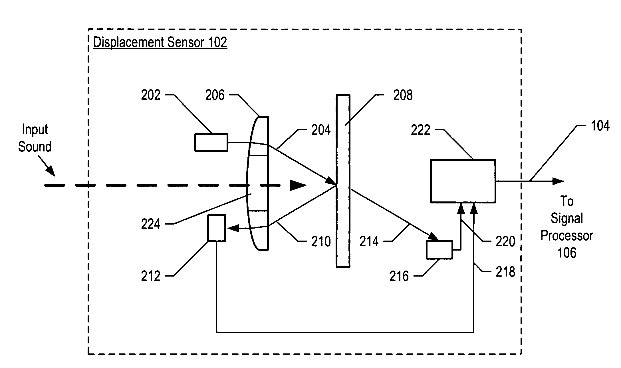
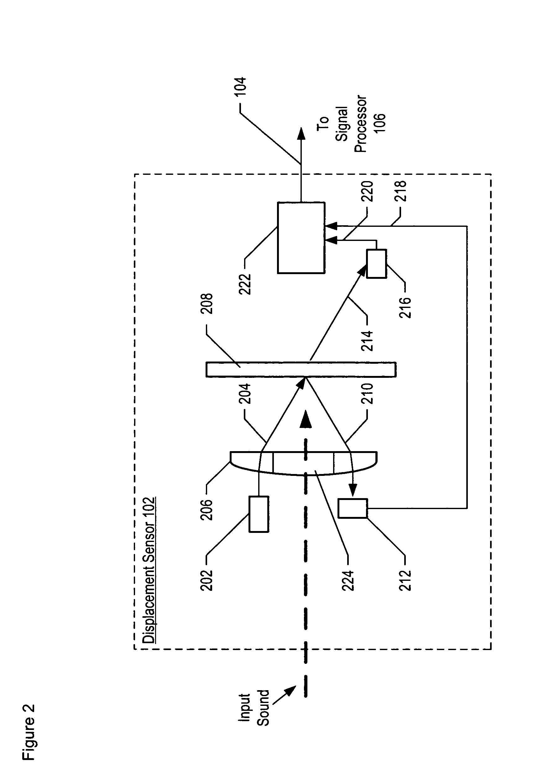
[0018]The following terms are defined for use in this Specification, including the appended claims:[0019]Optical device means a device that is capable of predictably or controllably affecting an optical signal, such as by absorption, reflection, diffraction, transmission, generating an optical signal, or processing an optical signal. Examples include passive optical devices, such as lenses, mirrors, switches, diffraction gratings, etc., and active optical devices, such as lasers, light-emitting diodes, etc.[0020]Fabry-Perot etalon means an optically-resonant cavity formed by two substantially parallel and substantially flat surfaces that are separated by a cavity length, wherein the cavity length is fixed.[0021]Fabry-Perot interferometer means an optically-resonant cavity formed by two substantially parallel and substantially flat surfaces that are separated by a cavity length, wherein the cavity length is not fixed. Examples include arrangements of plates wherein the cavity length ...


PUM

PropertyMeasurementUnit
spectral-widthaaaaaaaaaa

Abstract

An optical displacement sensor is disclosed that provides a high signal-to-noise ratio output signal without some of the disadvantages for doing so in the prior art. An embodiment of the present invention directs a light beam toward a Fabry-Perot interferometer and detects both the reflected and transmitted optical beams that result from interaction with the Fabry-Perot interferometer. Signal processing techniques are applied to signals based on both the reflected and transmitted beams, resulting in higher signal strength and / or reduced noise in the resulting output signal.

Description

FIELD OF THE INVENTION[0001]The present invention relates to displacement sensors in general, and, more particularly, to microphones.BACKGROUND OF THE INVENTION[0002]Displacement sensors, such as microphones and pressure sensors, are well-known. Displacement sensors based on capacitive, impedance, and optical measurements have been developed. Optical displacement sensors are particularly attractive as they overcome many of the limitations of capacitive and impedance measurement techniques, such as low sensitivity, the need for high voltage biasing, poor electrical isolation, or response nonlinearities.[0003]Many optical displacement sensors known in the prior art operate by detecting light reflected by an optical element that changes its reflectivity in response to a pressure differential, sound, vibration, etc. A Fabry-Perot interferometer has often been used as such an optical element. A Fabry-Perot interferometer is an optical element whose reflectivity depends on the spacing bet...

Claims


Application Information

Patent Timeline
Patent Type & Authority Patents(United States)
IPC IPC(8): G01B9/02G01L1/24
CPCG01H9/006G01L9/0079H04R23/008
Inventor CARR, DUSTIN WADE
Owner SYMPHONY ACOUSTICS
Why Eureka
Try Eureka