Triggering circuit for an aerosol drug-dispensing device

Inactive Publication Date: 2008-04-15
THE TECHNOLOGY PARTNERSHIP PLC
View PDF7 Cites 16 Cited by
  • Summary
  • Abstract
  • Description
  • Claims
  • Application Information

AI Technical Summary

Benefits of technology

[0012]The reference voltage may be derived from the bridge drive voltage, thus preventing erroneous triggering due to changes in ambient temperature.
[0013]The reference voltage may be derived from the bridge drive voltage and may be filtered to pass only low frequency signals. Thus, the reference voltage does not change appreciably with rapid changes in air flow whereas the unfiltered bridge drive voltage signal (the measurement drive) responds quickly to rapid changes in air flow. The sensitivity of the de

Problems solved by technology

Prior trigger circuits do not readily discriminate between a real triggering event, i.e. a patient inhaling on the device, and a false event, i.e. the movement of the device through the air or changes in

Method used


Image

  • Triggering circuit for an aerosol drug-dispensing device
  • Triggering circuit for an aerosol drug-dispensing device
  • Triggering circuit for an aerosol drug-dispensing device

Examples


Embodiment Construction

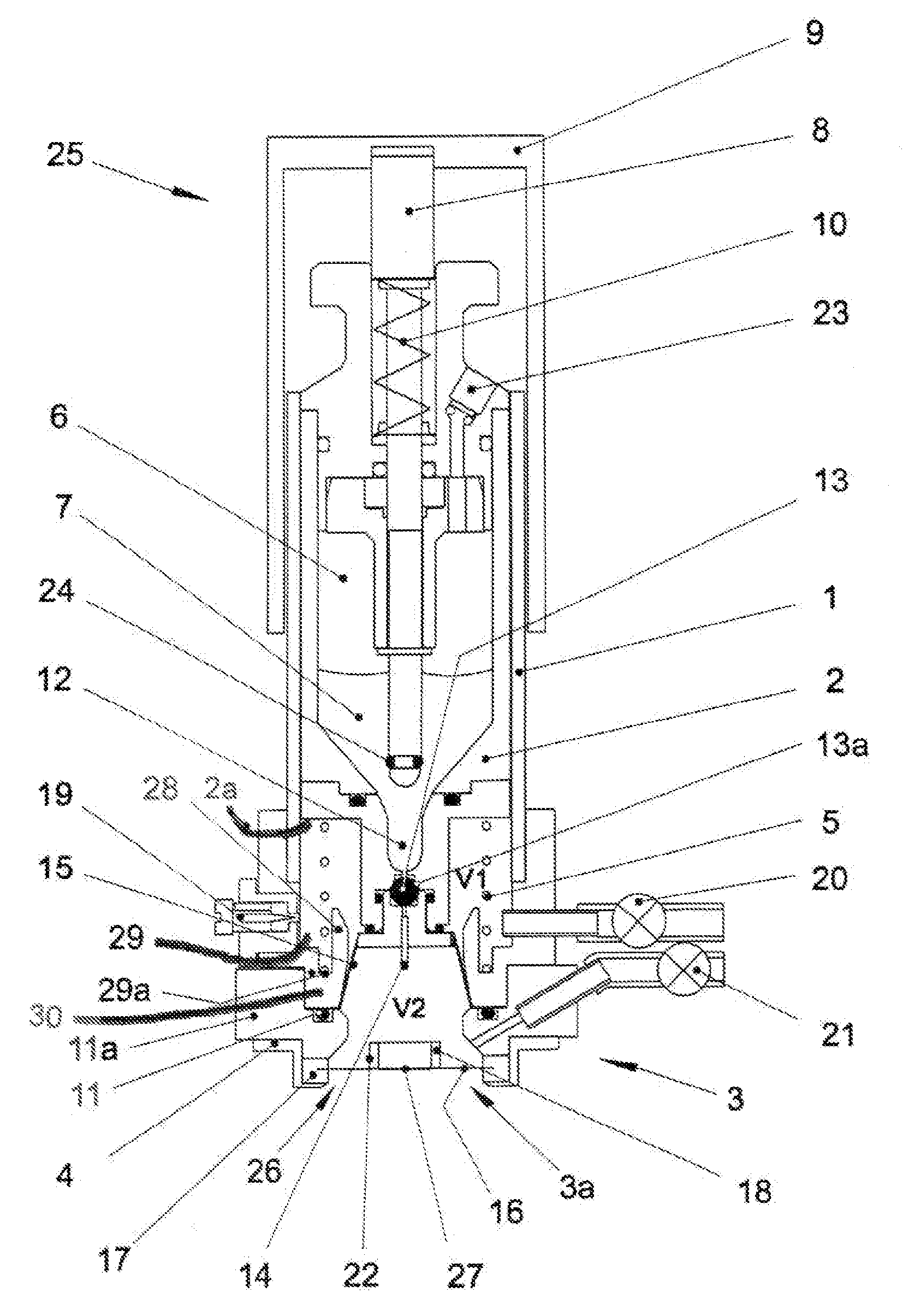
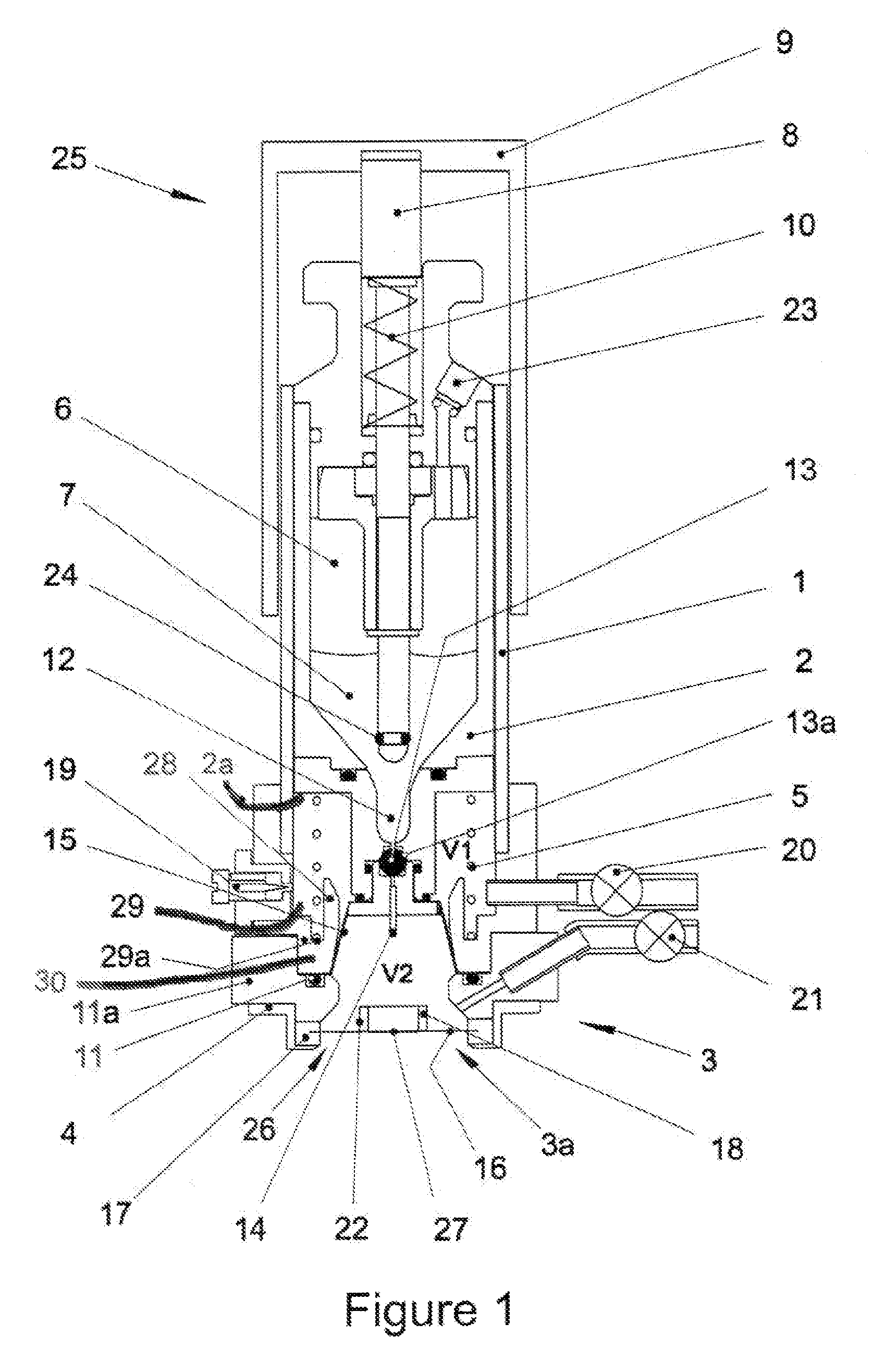
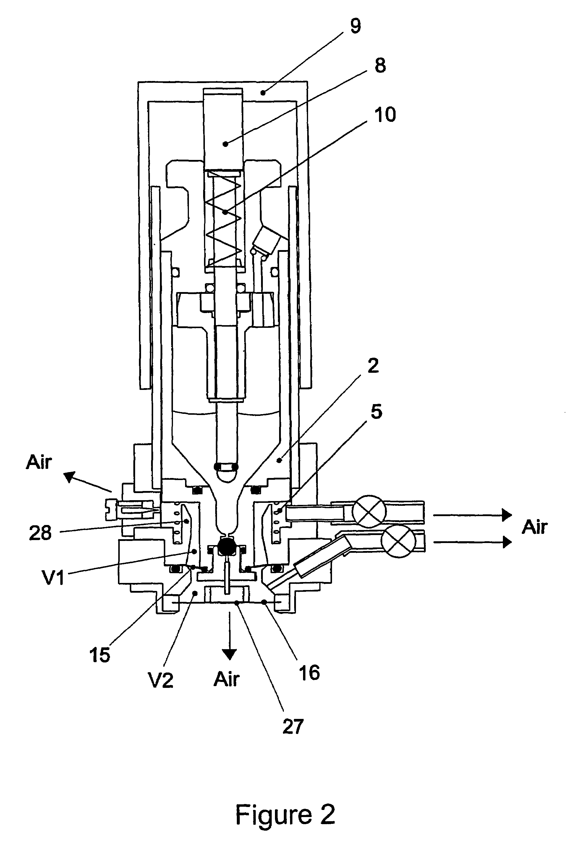
[0021]As can be seen from FIGS. 1 to 6, a drug dispensing device 25 forming part of a drug delivery system has a hollow casing 1 in which a reservoir body 2 is slidably mounted. A spray head mounting assembly 3 is attached to one end of the casing 1, the mounting assembly 3 comprising spray head assembly 3a, clamping means 4, diaphragm clamp 11a and seal 17. A main return spring 5 is provided in a recess 29 in the casing 1 between a lower face 2a of the reservoir body 2 and a notch 29a in diaphragm ring 30 to support the reservoir body 2, biassed towards its topmost position (as shown), within the casing 1. The reservoir body 2 is movable between a first and second position within the casing 1.

[0022]The reservoir body 2 has a reservoir cavity 6 in which a liquid drug 7 is stored and which can be topped-up via a re-fill port 23. A plunger 8 is provided within the reservoir body 2 and extends out of the upper (as shown in the figures) end of the reservoir body 2, such that it engages ...


PUM


Abstract

An electronic gas flow triggering circuit for use in an aerosol drug dispensing device has a voltage source and a self-nulling circuit to which voltage is supplied from the voltage source. A hot wire anemometer filament forms a component of the bridge circuit which is adapted to maintain a constant resistance of the anemometer filament, the bridge drive voltage being dependent upon the gas flow across the anemometer filament. A comparator compares the bridge output voltage with a reference voltage and provides a triggering signal to operate the device if the bridge drive voltage is greater than the reference voltage.

Description

BACKGROUND OF THE INVENTION[0001]This invention relates to a triggering circuit for use in an aerosol drug dispensing device, and in particular, to a triggering circuit for detecting the operation of the device by a user.[0002]Prior trigger circuits do not readily discriminate between a real triggering event, i.e. a patient inhaling on the device, and a false event, i.e. the movement of the device through the air or changes in ambient conditions. If the circuit were to be triggered by a false event, the device would be operated when the user was not ready to receive the drug and therefore that dose of the drug would be wasted. Thus, the present invention aims to provide a control circuit which overcomes the above problem.[0003]WO92 / 07599 discloses a portable inhalation device for the administration of medicament in the form of aerosolised fine particles or droplets of liquid to the respiratory system of a patient. The inhalation device comprises a bridge circuit which creates an ele...

Claims


Application Information

Patent Timeline
IPC IPC(8): A61M11/00A61M15/00A61M16/10G01P5/06A61M16/00B05B17/00G01P13/00
CPCA61M15/0065G01P13/006A61M2016/0039A61M2205/073
Inventor GOODCHILD, MARTIN SCOTT
Owner THE TECHNOLOGY PARTNERSHIP PLC
Why Eureka
Try Eureka