Axle structure for a motor vehicle

a technology for axles and motor vehicles, applied in the direction of understructures, resilient suspensions, pivoted suspension arms, etc., can solve the problem of increasing costs

Inactive Publication Date: 2008-04-15
BENTELER AUTOMOBILTECHNIK GMBH
View PDF19 Cites 8 Cited by
  • Summary
  • Abstract
  • Description
  • Claims
  • Application Information

AI Technical Summary

Benefits of technology

[0008]The provision of identically configured shells results not only in less tool costs but also in a significant reduction in logistics. As the shells are bonded by one or more cement layers, shape tolerances have essentially no effect on the joining process. The axle structure is simple while still providing sufficient space for receiving bearings in the area of the necks. The sandwich construction of the axle structure in the form of identical shells that are cemented together permits realization of significant moments of inertia while having substantial structural stiffness. By applying adhesive at a selected length in longitudinal direction of the longitudinal beams as well as to the cross member including the areas of the necking, buckling strength and twist stiffness of the axle structure can be tailored as desired.
[0012]According to another feature of the present invention, each of the first and second cement layers may be polyurethane foam or epoxy adhesive for joining the shells. Of course, also any combination of polyurethane foam and epoxy adhesive may be conceivable in different spaced-apart sections of the axle structure for joining the shells. In this way, static and dynamic load behavior can be influenced. For example, a cement layer of epoxy adhesive may be applied in the area of the necks, while a cement layer of polyurethane foam may be applied in central length sections of the longitudinal beam as well as cross member. In this way, different sections may vary in buckling strength and twist stiffness.

Problems solved by technology

This increases costs.

Method used


Image

  • Axle structure for a motor vehicle
  • Axle structure for a motor vehicle
  • Axle structure for a motor vehicle

Examples


Embodiment Construction

[0018]Throughout all the figures, same or corresponding elements are generally indicated by same reference numerals. The depicted embodiment is to be understood as illustrative of the invention and not as limiting in any way. It should also be understood that the drawings are not necessarily to scale and that the embodiments are sometimes illustrated by graphic symbols, phantom lines, diagrammatic representations and fragmentary views.

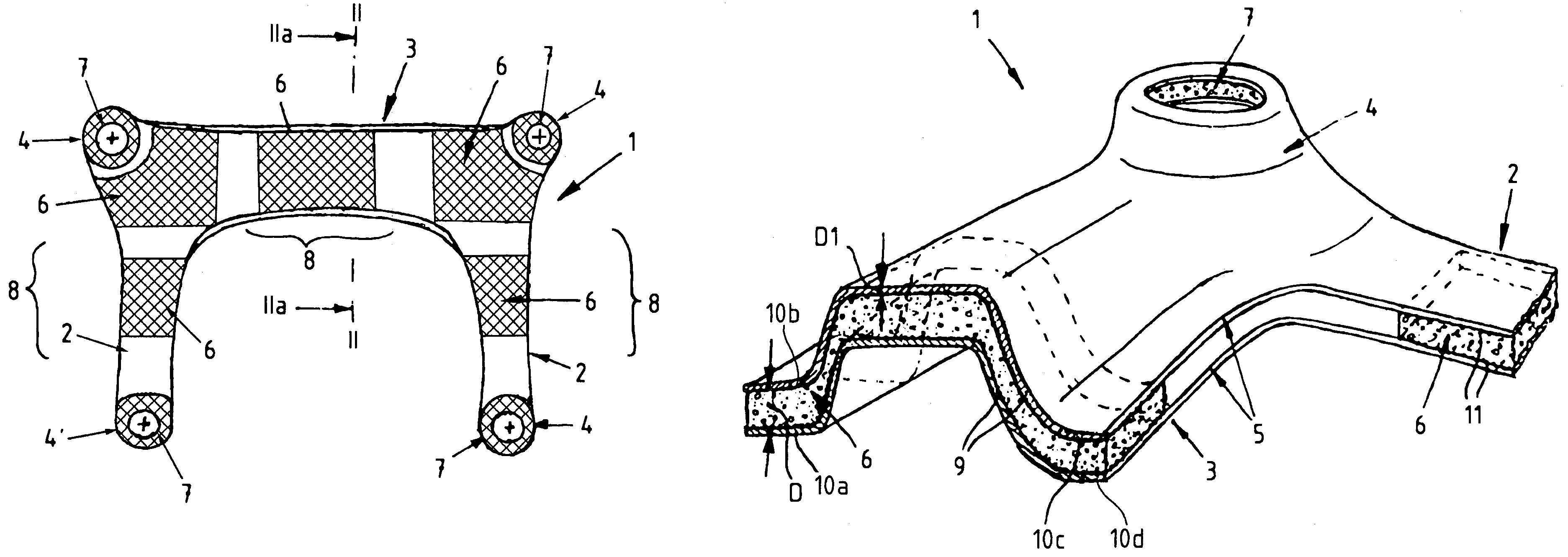
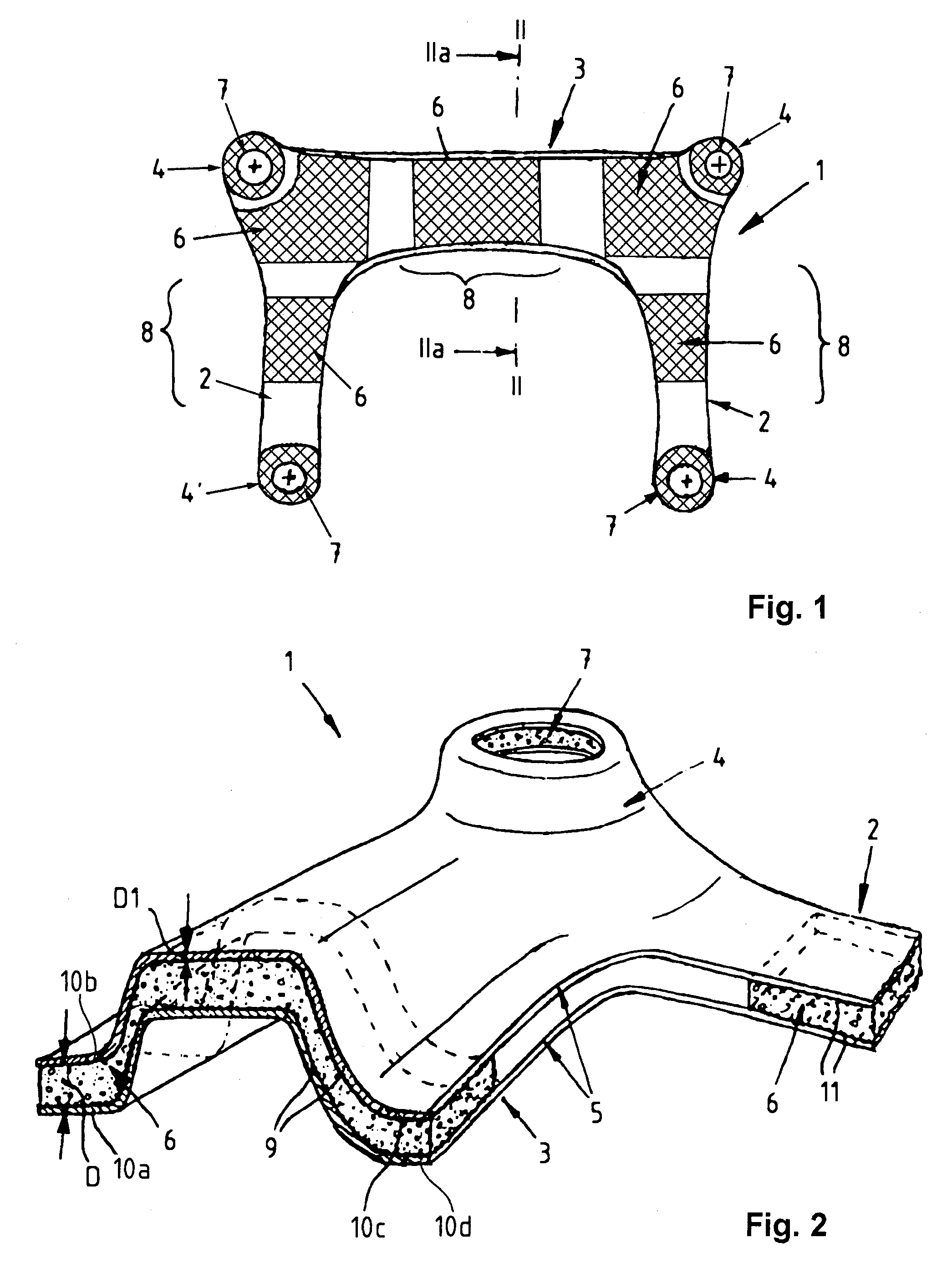
[0019]Turning now to the drawings, and in particular to FIG. 1, there is shown a schematic illustration of an axle structure according to the present invention, generally designated by reference numeral 1, for use in an unillustrated motor vehicle, especially passenger car. The axle structure 1 has a body of U-shaped configuration and includes two longitudinal beams 2 and a cross member 3 interconnecting the longitudinal beams 2 at one end thereof. Each cross-member-proximal end of the longitudinal beams 2 is formed with a neck 4, and each cross-member...


PUM


Abstract

An axle structure for a motor vehicle includes a body of U-shaped configuration with two longitudinal beams and a cross member interconnecting the longitudinal beams at one end thereof. Each longitudinal beam has ends formed as a neck. The longitudinal beams and the cross member are made of two identical metallic shells which extend in congruent relationship and are cemented to one another at least in sections thereof in sandwich-like manner.

Description

CROSS-REFERENCES TO RELATED APPLICATIONS[0001]This application claims the priority of German Patent Application, Serial No. 10 2004 055 100.6, filed Nov. 15, 2004, pursuant to 35 U.S.C. 119(a)-(d), the subject matter of which is incorporated herein by reference.BACKGROUND OF THE INVENTION[0002]The present invention relates, in general, to an axle structure for a motor vehicle.[0003]Nothing in the following discussion of the state of the art is to be construed as an admission of prior art.[0004]Axle structures, also called sub-frames come in many variations, e.g. as a single shell sheet-steel module or double shell steel-sheet construction, whereby both constructions may be provided with reinforcements of sheet metal. Single shell axle structures have in general little stiffness, whereas double shell axle structures require a joining operation to connect the shells, normally by welding. This increases costs.[0005]It would therefore be desirable and advantageous to provide an improved...

Claims


Application Information

Patent Timeline
Patent Type & Authority Patents(United States)
IPC IPC(8): B60G21/055
CPCB60G7/02B62D21/11B60G2204/15B60G2206/013B60G2206/60B60G2206/602B60G2206/605
Inventor ZUBER, ARMIN
Owner BENTELER AUTOMOBILTECHNIK GMBH
Why Eureka
Try Eureka