Image detector for bank notes

a technology for image detectors and bank notes, applied in the field of image detectors for bank notes, can solve the problems of increasing costs, and achieve the effect of increasing comparability and highlighting differences in associated image data

Active Publication Date: 2008-04-15
LAUREL PRECISION MACHINES
View PDF26 Cites 27 Cited by
  • Summary
  • Abstract
  • Description
  • Claims
  • Application Information

AI Technical Summary

Benefits of technology

[0025]Because in this manner, the first light emitting device, the second light emitting device, and the third light emitting device each irradiate visible light, infrared light and ultraviolet light, differences in associated image data can be made conspicuous and comparability can be increased.

Problems solved by technology

Since three image detection sensors are required for the respective light receptions, there is a problem in that cost is increased.

Method used


Image

  • Image detector for bank notes
  • Image detector for bank notes
  • Image detector for bank notes

Examples


first embodiment

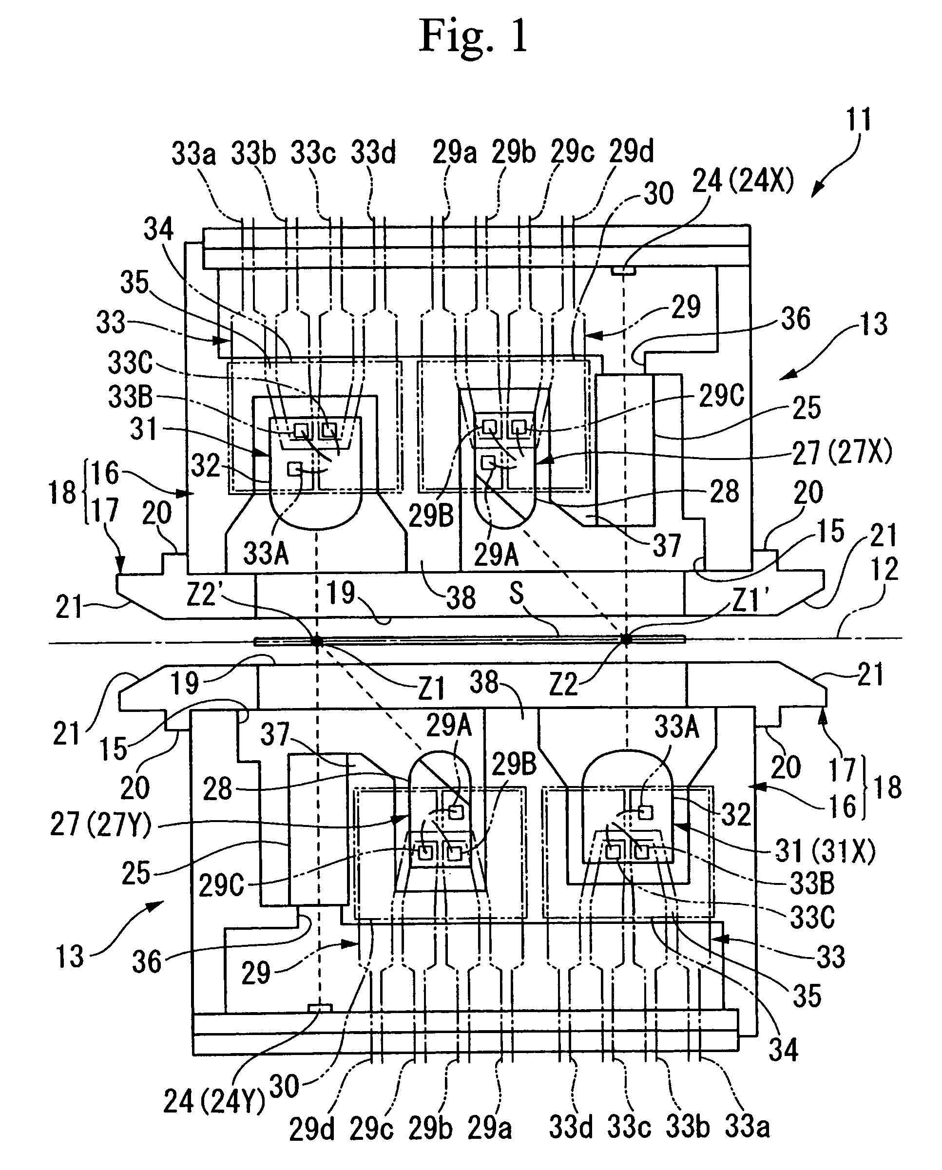
[0036]An image detector for bank notes according to the present invention is described below with reference to FIG. 1 through FIG. 4.

[0037]As shown in FIG. 1, an image detector for bank notes 11 of the first embodiment comprises a pair of identically constructed detection units 13, arranged so as to oppose each other across a bank note transportation path 12 which transports a bank note S in a straight line.

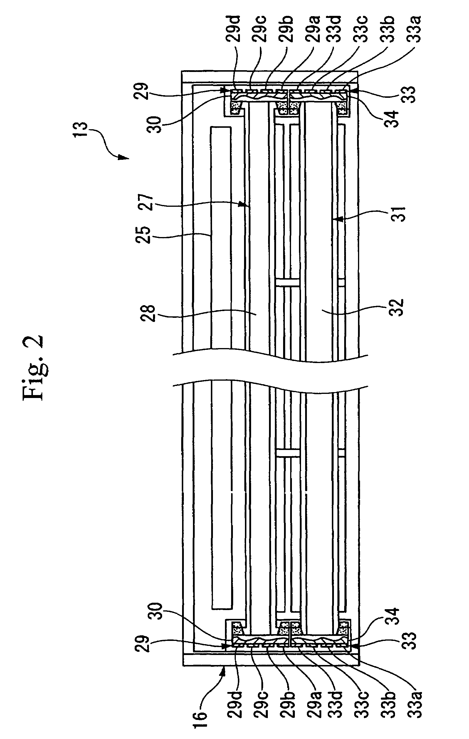
[0038]The dimensions of the detection unit 13 are substantially larger in the length direction (the direction orthogonal to the paper surface in FIG. 1) than in the thickness direction (the vertical direction in FIG. 1) and the width direction (the crosswise direction in FIG. 1), giving the detection unit 13 an elongated shape. The detection unit 13 has a unit main body 18, comprising a housing body 16 in the shape of an elongated box with an opening 15 provided on one side in the thickness direction of the detection unit 13, and a flat elongated translucent cover 17 mounted to t...

second embodiment

[0083]Together with this, the acquisition control device 47 of the second embodiment, takes in to a first image memory region of a memory 42, a plurality, specifically four image datas detected by the first CCD sensor 24 (24X) at detection timings respectively synchronized with the light emissions of the first light emitting body 31 (31X) and the second light emitting body 27 (27X), and which are AD converted by the AD converter 41 via a multiplexer 48, and also takes in to a second image memory region of the memory 42, a plurality, specifically two image datas detected by the second CCD sensor 24 (24Y) at detection timings respectively synchronized with the light emissions of the third light emitting body 27 (27Y), and which are AD converted by the AD converter 41 via the multiplexer 48.

[0084]In this manner, because the acquisition control device 47 is only one, the timing is controlled so that the detection timings of the image data of the first CCD sensor 24 (24X) and the detecti...

third embodiment

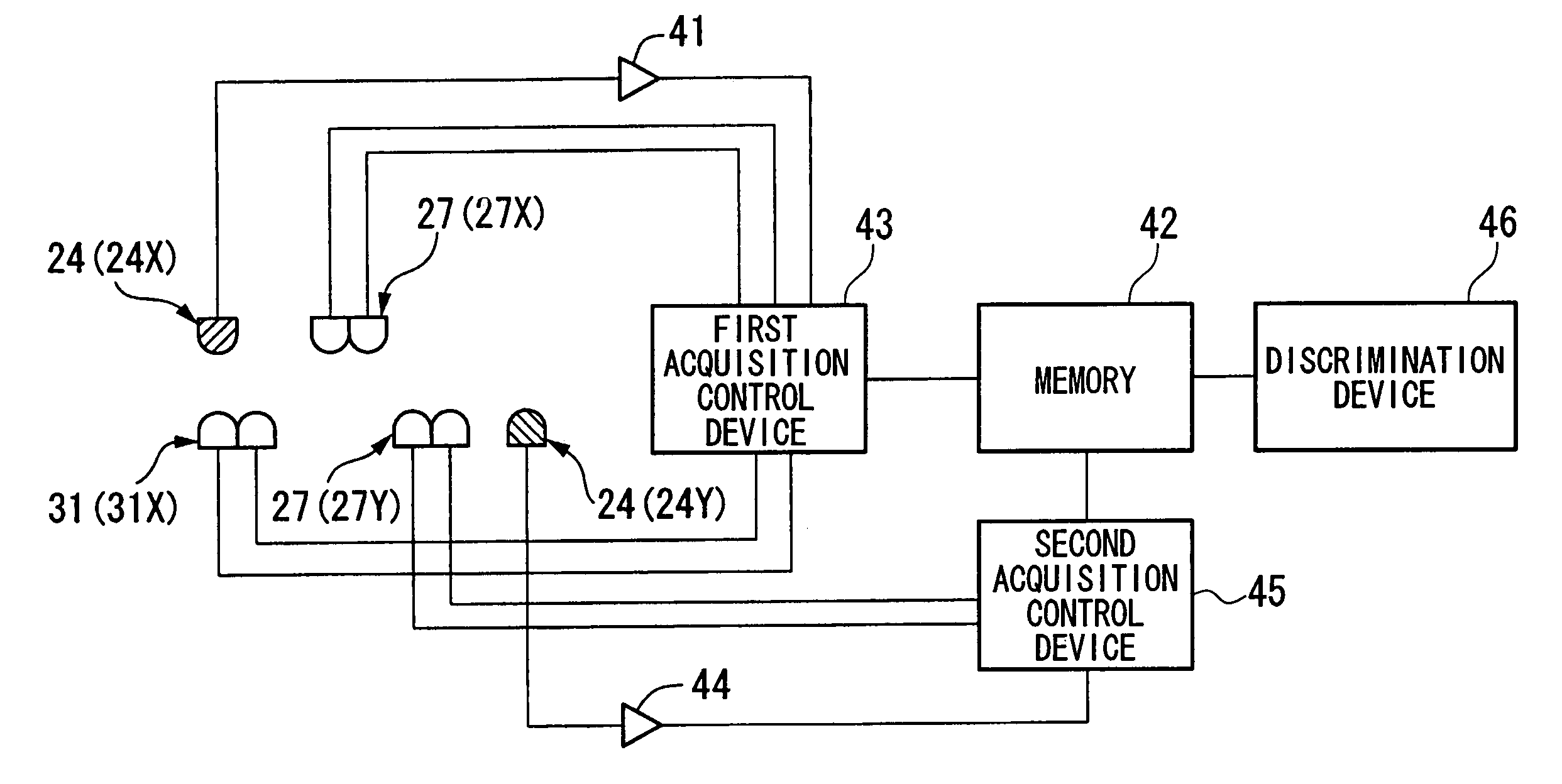
[0091]That is to say, in the third embodiment, as shown in FIG. 7, a first acquisition control device 43 only emits light of three different wavelength ranges from the first light emitting body 31 (31X), at respective different light emission timings, by for example drive of the LED elements 33A, 33B and 33C, and also only emits light of a three different wavelength ranges from the second light emitting body 27 (27X), at respective different light emission timings which are also different light emission timings to the first light emitting body 31 (31X), by for example drive of the LED elements 29A, 29B and 29C, and together with this, takes in to a first image memory region of a memory 42, six image datas detected by the first CCD sensor 24 (24X) at detection timings respectively synchronized with the light emissions of the first light emitting body 31 (31X) and the second light emitting body 27 (27X), and which are AD converted by the AD converter 41.

[0092]Furthermore, in the third...


PUM


Abstract

An object is to provide an image detector for bank notes which enables the cost to be lowered. Accordingly this has: a light emitting device 31 (31X) which is arranged facing an image detection sensor 24 (24X), and which irradiates light of a plurality of different wavelengths ranges towards a bank note on a bank note transportation path 12, and detects light of the light which has transmitted through the bank note with an image detection sensor 24 (24X); a light emitting device 27 (27X) which is provided on the same side as the image detection sensor 24 (24X), which irradiates light of a plurality of different wavelengths ranges towards a bank note S, and detects light of the light which is reflected from the bank note with the image detection sensor 24 (24X); an image detection sensor 24 (24Y) provided on the opposite side to the image detection sensor 24 (24X); and a third light emitting device 27 (27Y) provided on the same side as the second image detection sensor 24 (24Y), which irradiates light of a plurality of different wavelength ranges towards the bank note S, and detects light of the light which is reflected from the bank note S with the image detection image detection sensor 24 (24Y).

Description

RELATED APPLICATIONS[0001]This application is related to, and hereby incorporates by reference, U.S. patent application entitled “IMAGE DETECTOR FOR BANK NOTES”, filed on even date herewith and having application Ser. No. 10 / 854,578.BACKGROUND OF THE INVENTION[0002]1. Field of the Invention[0003]The present invention relates to an image detector for bank notes which is used when discriminating between bank notes.[0004]2. Description of Related Art[0005]Technology relating to image detectors for bank notes used for example when discriminating the authenticity, denomination and state of wear of bank notes, includes technology in which a light emitting unit arranged on one side of a bank note transportation path irradiates light onto a bank note, and the light transmitted through the bank note is detected by a light receiving unit arranged on the other side of the bank note transportation path, and technology in which light is irradiated onto a bank note from a light emitting section a...

Claims


Application Information

Patent Timeline
Patent Type & Authority Patents(United States)
IPC IPC(8): G06K9/00G06T1/00G07D7/12G07D7/182
CPCG07D7/121G07D7/18G07D7/181G07D11/225G07D7/12G07D2207/00G07D2211/00
Inventor TSUJI, KEIJIKASAI, TOSHIOZENKI, TOMOYOSHI
Owner LAUREL PRECISION MACHINES
Why Eureka
Try Eureka