[0016]As the V-type engine is arranged with the bisector of the banking angle of the V-type engine directed
toward the head pipe, the banking angle can be set to a large angle equal to or exceeding approximately 90°. The low floor type vehicle can be also made more advantageous for the vibration of the V-type engine by increasing the banking angle and a large space for arranging the intake
system including intake
coupling pipes for each cylinder and an
air cleaner can be secured by increasing the banking angle. Therefore, the degree of freedom in designing the intake
system is enhanced.
[0018]As the body frame is the
diamond type frame and the V-type engine is suspended from the
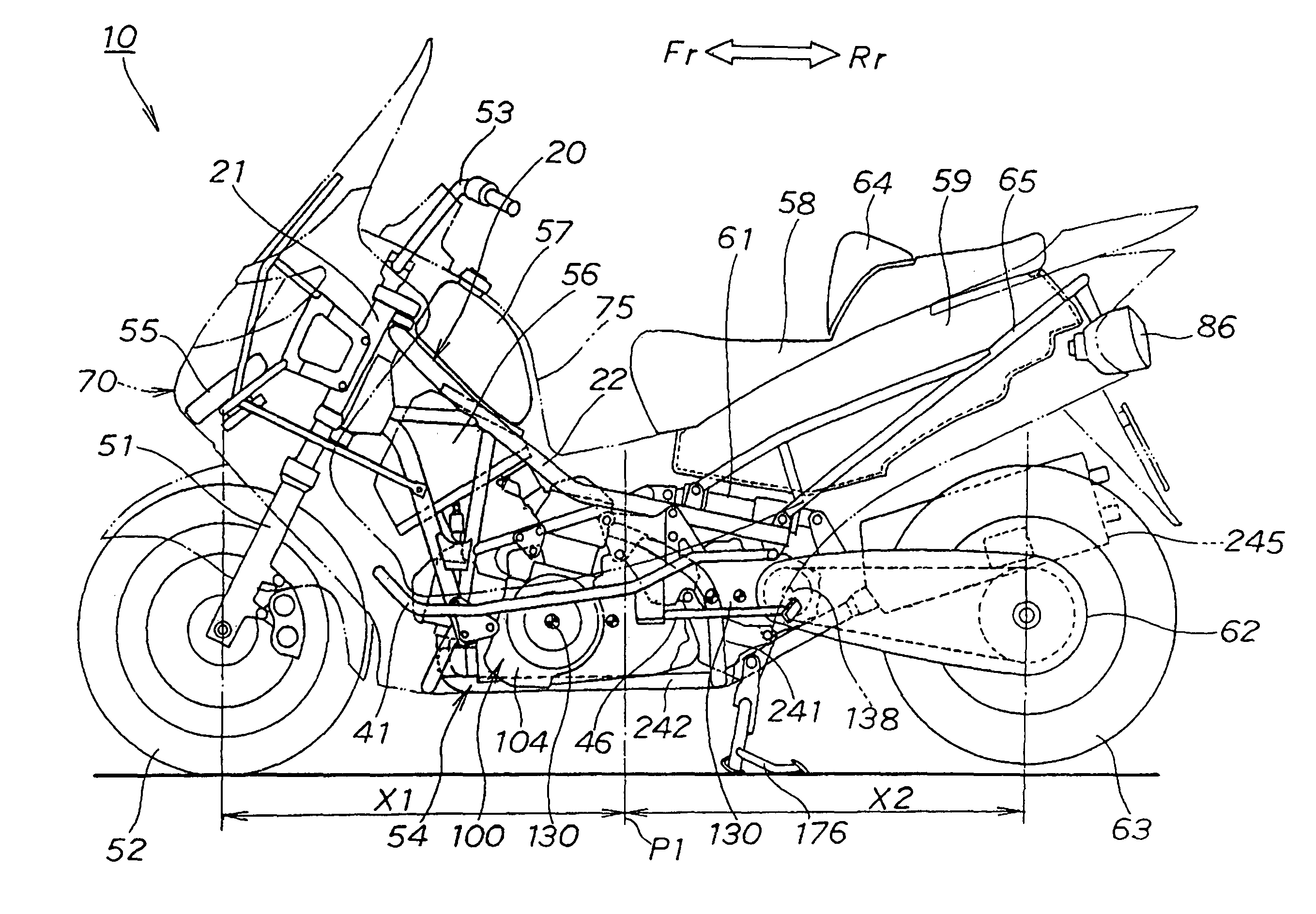
diamond type frame, the engine can function as a part of the body frame. Therefore, a frame member is not required to be arranged below the V-type engine. Therefore, the V-type engine can be lowered maximally up to the height of the ground. As a result, as a
crankshaft of the V-type engine is also lowered, larger space can be acquired above a low floor. Hereby, the degree of freedom in designing the V-type engine having a banking angle equal to or exceeding approximately 90° can be enhanced. In addition, the center of gravity of the low floor type vehicle can be lowered by lowering the V-type engine and the vibration can be reduced.
[0020]The V-type engine can be arranged as in front as possible by arranging the front cylinder in the
bank of the V-type engine in front of the right and left down frames. As a result, as the center of gravity of the low floor type vehicle can be set more in front, and the load applied to a front wheel and a rear wheel can be more suitably distributed.
[0021]Further, the position of the
crankshaft of the V-type engine is shifted forward by arranging the front cylinder in the
bank in front. In this case, the bisector of the banking angle is also directed
toward the head pipe. As the bisector of the banking angle is closer to a vertical line in which the position of the
crankshaft is shifted forward, the rear cylinder in the
bank is inclined toward the rear of the body according to it. Therefore, the height of the rear cylinder in the bank can be lowered. Therefore, the degree of freedom in mounting the V-type engine is enhanced.
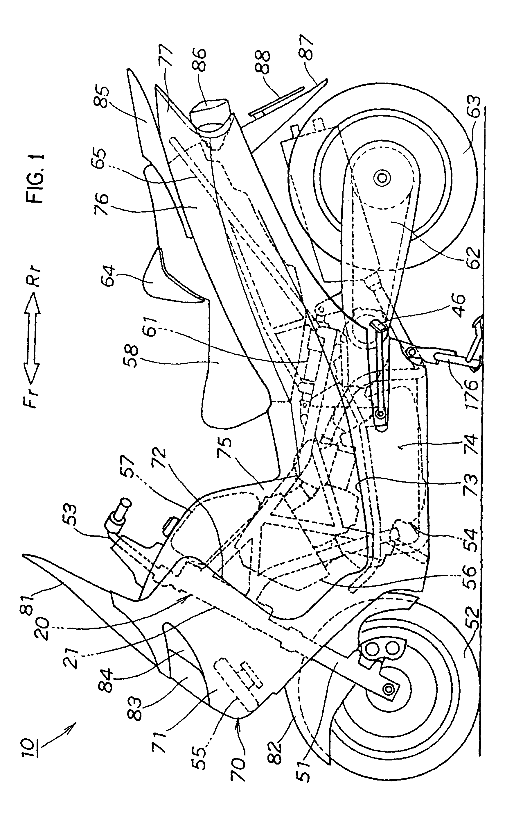
[0023]As the rear cylinder in the bank of the V-type engine is arranged between the right and left upper frames, the lowered upper frames do not interfere with the rear cylinder in the bank. Therefore, the upper frames can be arranged in as a low position as possible. Therefore, as the center of gravity of the body frame is lowered, the center of gravity of the low floor type vehicle can be lowered. In addition, as the low floor can be made lower, the driving of the low floor type vehicle is facilitated. Further, when a rider rides, he / she can more easily
straddle the body frame when the upper frames are lowered.
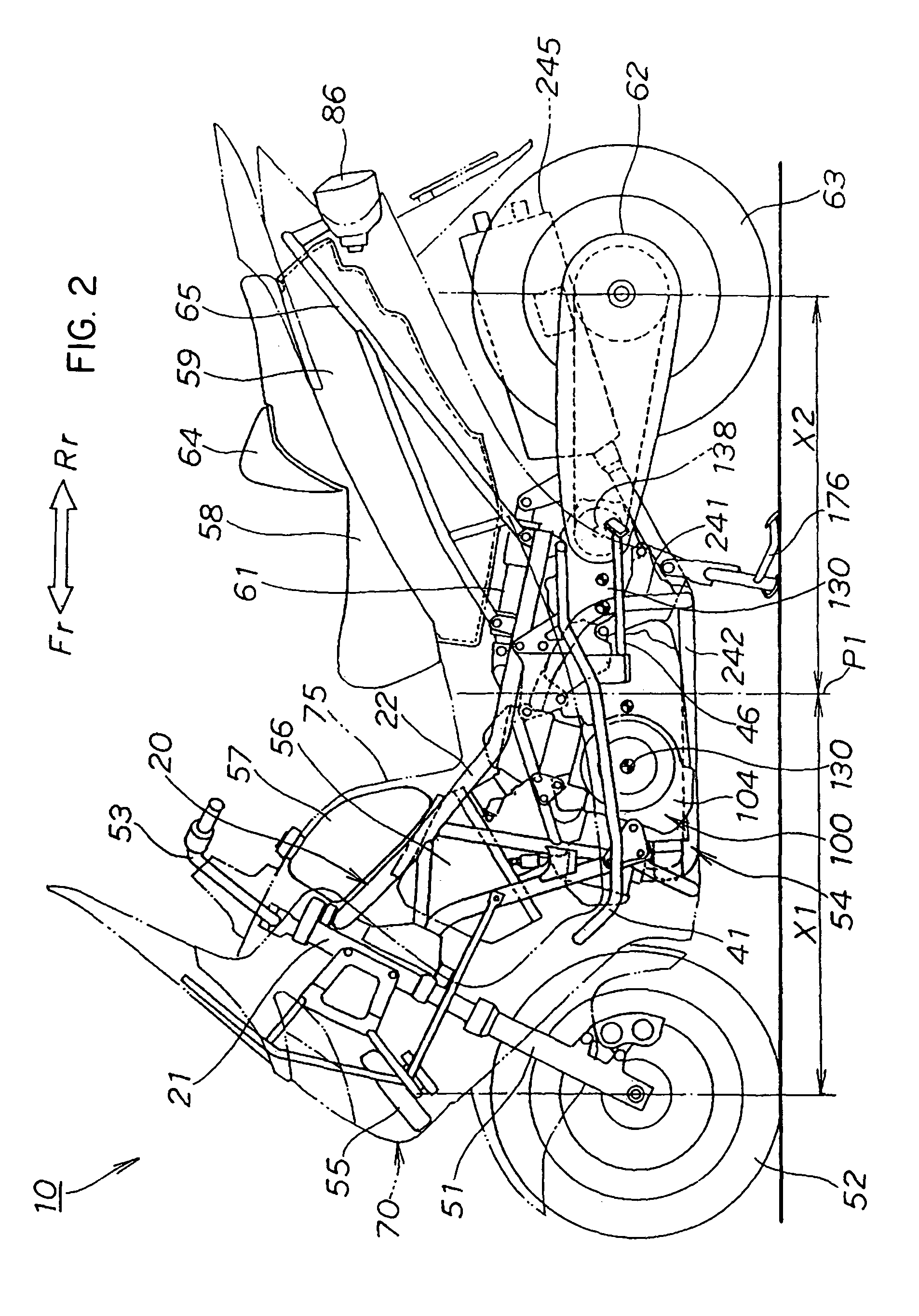
[0025]As the bisector of the banking angle is directed
toward the head pipe, large space can be secured among the cylinders in the V-type bank and the head pipe. As the intake
system including the intake
coupling pipes and the
air cleaner is arranged in such large space between the cylinders in the V-type bank with the intake system directed toward the head pipe, the intake system and the V-type engine can be efficiently coupled and the performance of the V-type engine can be enhanced. Besides, the intake system can be miniaturized and collected in a relatively low position. Therefore, the
fuel tank can be easily arranged above the low intake system and the
mass can be collected in the front. As the center of gravity of the low floor type vehicle can be set in the front by arranging the
fuel tank in the front of the low floor type vehicle, a load applied to the front wheel and the rear wheel can be more suitably distributed. In addition, as the
fuel tank is not required to be arranged under the seat, a large space is secured under the seat and a housing box having a large space is possible.

