Dipole antenna

a dipole antenna and antenna technology, applied in the direction of antenna arrays, electrical devices, radiation elements, etc., can solve the problems of affecting the performance of the series-fed antenna, so as to achieve stable grounding arrangement, suitable matching, and simple manufacturing methods

Active Publication Date: 2008-04-29
RF IND
View PDF8 Cites 18 Cited by
  • Summary
  • Abstract
  • Description
  • Claims
  • Application Information

AI Technical Summary

Benefits of technology

[0031]The antenna array preferably further includes a central support shaft, wherein each antenna member in the array is mounted coaxially along the length of the shaft. In preferred embodiments, the dipole antenna members in the array are mounted approximately equally distant from one another, however it is an advantage of the present invention that the precise placement of the antenna members is not especially critical. For example, the centre-to-centre spacing of the dipole antenna members may be approximately within the range of 0.6 to 1 wavelength, and the low sensitivity to the location of the individual dipoles may result in greater ease of assembly, and a corresponding reduced cost of manufacture.
[0032]It is particularly preferred that the central support shaft be grounded, and that a ground conductor of the feed line feeding each antenna member be in electrical contact with the shaft. In a particularly preferred embodiment, the substrate of each dipole antenna member is formed around a metallic disc which includes a central hole, through which the support shaft passes, and which is in electrical contact with one of the radiating elements, such that an extremely stable grounding arrangement is provided.
[0033]In yet another aspect, the invention provides a method of manufacturing a dipole antenna, including the steps of:
[0034]forming first and second radiating elements on the surface of a flexible substrate, the radiating elements including respective feed points for making operative electrical contact with a feed line including corresponding first and second feed conductors, wherein the radiating elements are arranged on the substrate such that in use an input impedance of the dipole antenna is substantially matched to a characteristic impedance of the feed line over a selected frequency band;
[0035]forming the flexible substrate into a substantially cylindrical shape having a longitudinal axis; and
[0036]wherein the first and second radiating elements are formed on the substrate such that they are disposed in a substantially collinear arrangement parallel to said longitudinal axis.

Problems solved by technology

However, most types of series-fed antenna inherently possess a narrow bandwidth.
The resulting cumulative change in phase degrades the antenna performance at such frequencies, by causing the peak of the radiated beam to tilt up and down with increasing and decreasing frequency, thereby causing variations in radiation intensity at the horizon.
However, the cables and the mast of such antennas act as parasitic elements which reflect energy, resulting in a cardioid pattern, rather than circular pattern, of radiation emitted by each dipole.
The necessity to ensure accurate positioning of the individual antenna elements leads to increased complexity and cost in the design and construction of antennas of this type.
Furthermore, the large number of mechanical and electrical joints that may be required in the assembly of antennas formed from individual cylindrical elements may result in other forms of degradation in antenna performance.
In particular, electrical and mechanical joints between individual metallic components of an antenna may result in a parasitic non-linear response, causing a form of degradation known as Passive Inter-Modulation distortion (PIM).
It may be very difficult to meet this specification with an antenna having a large number of mechanical joints, in addition to which the long-term stability of antenna performance may be an issue.
For example, an antenna deployed in a typical mobile telephony application will be mounted on a tower where it is subjected over time to wind, electrical hum and mechanical vibrations which may cause mechanical joints to shift or loosen, resulting in degradation of PIM performance over time.

Method used


Image

  • Dipole antenna
  • Dipole antenna
  • Dipole antenna

Examples


Embodiment Construction

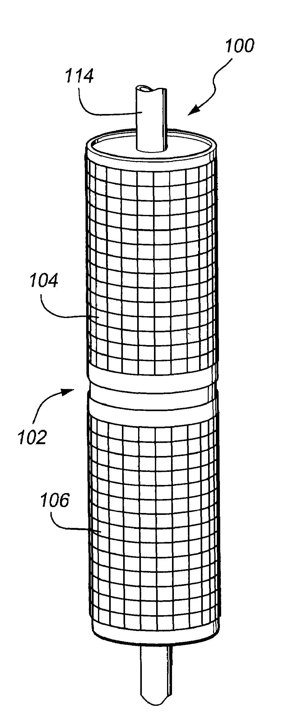
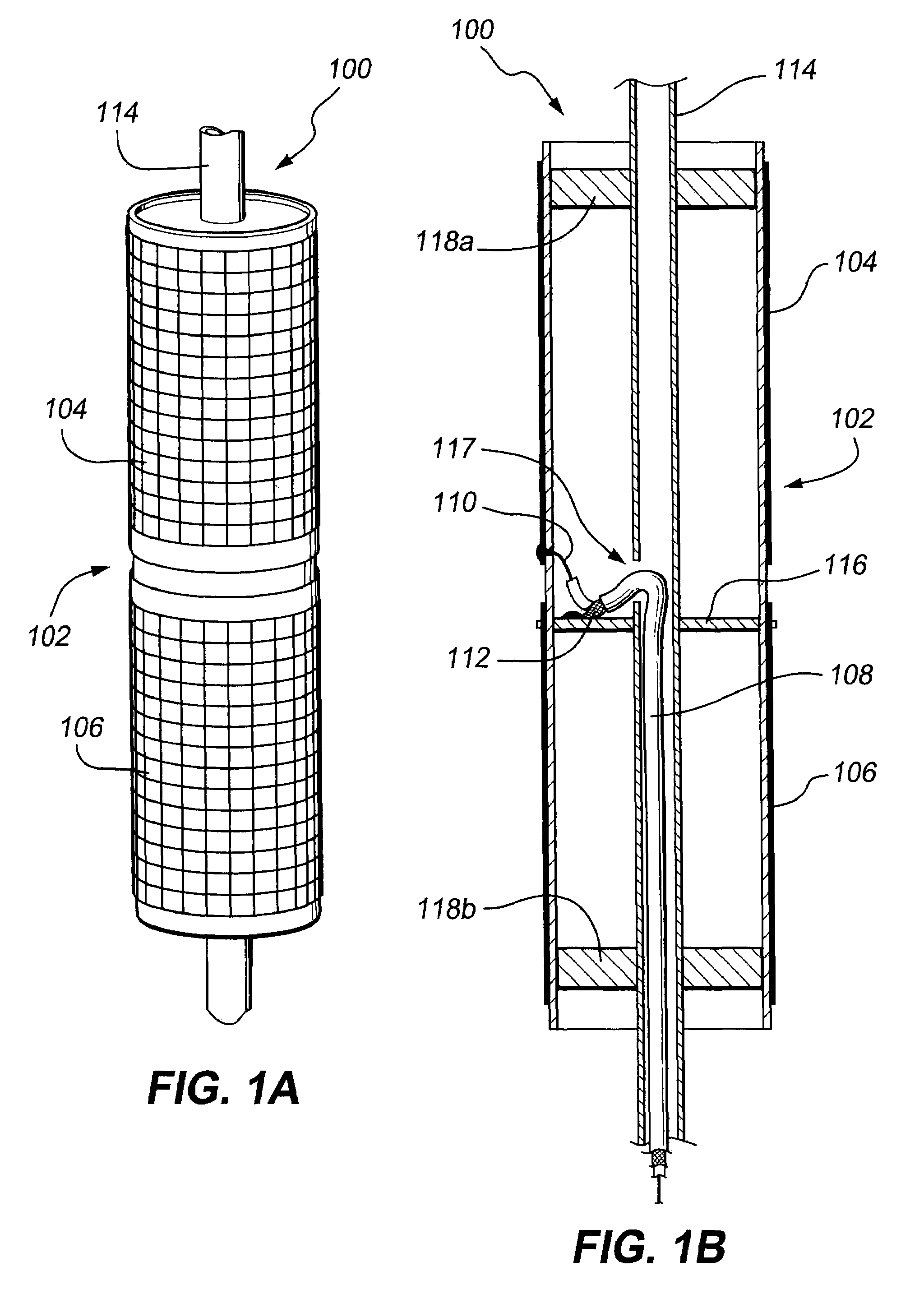
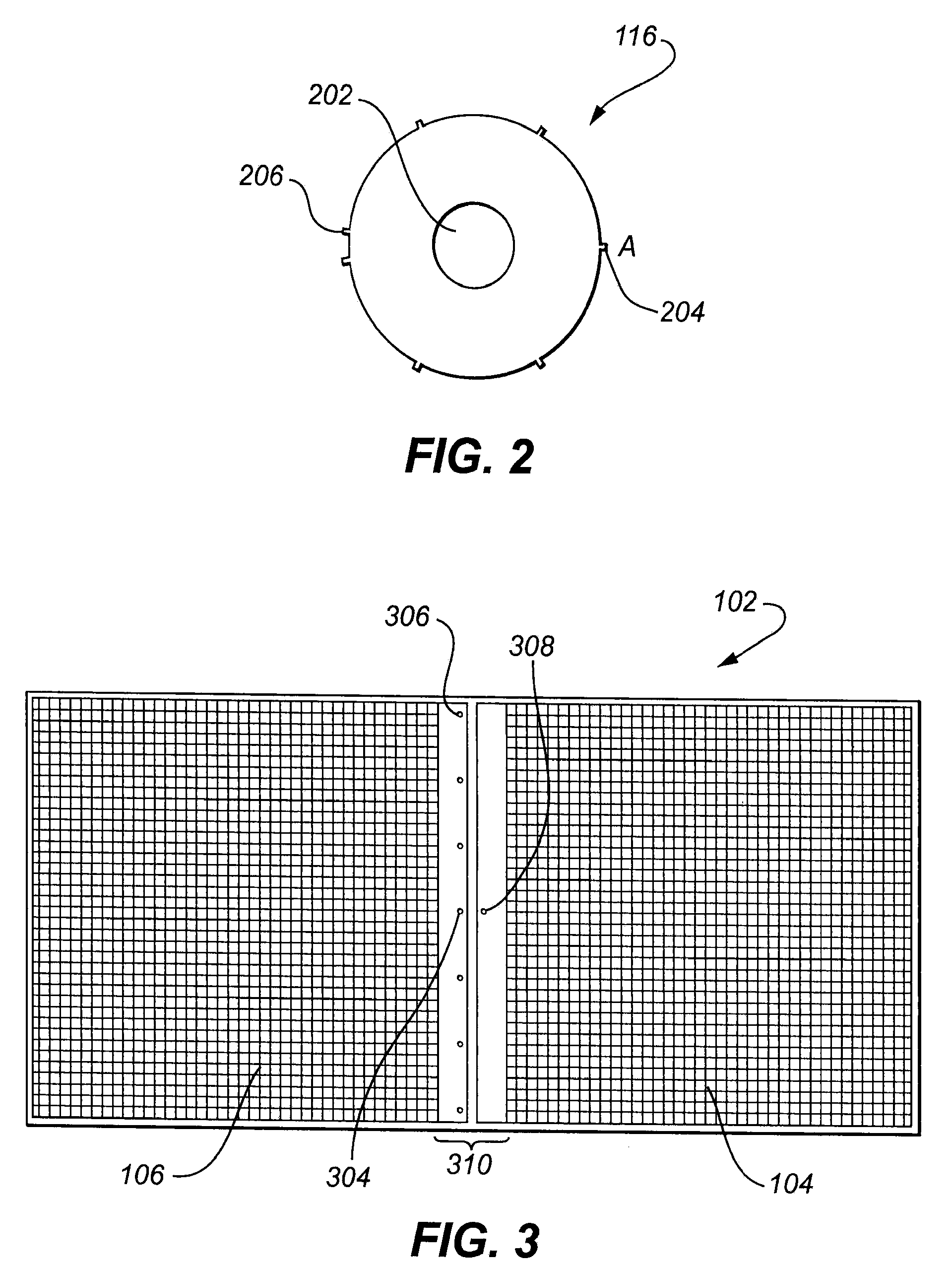
[0050]Referring firstly to FIGS. 1A and 1B there is illustrated, in perspective and cross-sectional views respectively, an antenna 100 according to an embodiment of the present invention. The antenna 100 includes an integral dipole antenna member 102, having first and second radiating elements 104, 106 disposed on the surface of a flexible substrate, which has been formed into a substantially cylindrical shape. The antenna 100 further includes a feed network, including at least the coaxial cable feed line 108 having first, central, conductor 110 and second, outer, conductor 112.

[0051]It will be appreciated that, as used herein, the terms “feed”, “feed line”, “feed conductor”, “feed network” and so forth are intended to include bi-directional as well as uni-directional circuits, encompassing arrangements for the transmission of signals both to and from the antenna 100. As such, coaxial feed line 108 is provided to conduct signals to and from the radiating elements 104, 106.

[0052]The ...


PUM


Abstract

A method of manufacturing a dipole antenna comprises the steps of forming first and second radiating elements on the surface of a flexible substrate, the radiating elements including respective feed points for making operative electrical contact with a feed line including corresponding first and second feed conductors. The radiating elements are arranged on the substrate such that, in use, an input impedance of the dipole antenna is substantially matched to a characteristic impedance of the feed line over a selected frequency band. The flexible substrate is then formed into a substantially cylindrical shape. The resulting antenna comprises an integral dipole antenna member having radiating elements disposed on a surface of a substantially cylindrical substrate. The antenna avoids the need to separately manufacture the radiating elements, and subsequently to assemble the elements to form a dipole antenna. The antenna is simple to construct, has a relatively low number of mechanical and electrical joints and contacts, and may provide improved mechanical stability and electrical performance as compared with prior art antennas.

Description

FIELD OF THE INVENTION[0001]The present invention relates to antenna devices, and more particularly to corporately-fed collinear array dipole antennas, such as are commonly used in mobile radio and telephone communication systems, in which signals must be transmitted and received over a wide range of angles around the antenna.BACKGROUND OF THE INVENTION [0002]Collinear array dipole antennas are well known for providing radiation over a wide range of angles around the antenna, and more particularly for providing omnidirectional radiation. Known types of collinear array antennas include the Franklin antenna, which is a series-fed collinear array typically manufactured using a coaxial cable feed line, as well as other, similar, structures. Such antennas generally include a series-fed sequence of end-fed, half wavelength radiators, which produce a substantially uniform circular radiation pattern in the azimuth.[0003]However, most types of series-fed antenna inherently possess a narrow b...

Claims


Application Information

Patent Timeline
Patent Type & Authority Patents(United States)
IPC IPC(8): H01Q9/16
CPCH01Q1/38H01Q9/065H01Q9/18H01Q9/20H01Q21/062
Inventor DWYER, BRADLEY LANCEARMSTRONG, WARWICK THOMASDALY, ROBERT ANDREWMEZZAPICA, MARK ANTHONY
Owner RF IND
Why Eureka
Try Eureka