Activating a vehicle's own brake lights and/or brakes when brake lights are sensed in front of the vehicle, including responsively to the proximity of, and/or rate of closure with, a forward vehicle

a technology of brake lights and brakes, applied in the field of vehicle safety, can solve the problems of a large number of deaths, more than three million injuries, and a large amount of financial losses, and achieve the effects of reducing the number of deaths, increasing the cost of operation, and increasing the number of injuries

Inactive Publication Date: 2008-04-29
BRAKE
View PDF7 Cites 139 Cited by
  • Summary
  • Abstract
  • Description
  • Claims
  • Application Information

AI Technical Summary

Benefits of technology

[0020]The present invention contemplates a vehicular system, and method, that senses the incipient occurrence of brake lights to the front of a subject vehicle and, in response to sensed brake lights, effectively activates (i) the subje

Problems solved by technology

However, each year motor vehicle crashes in the U.S. still account for a staggering 45,000 deaths, more than three million injuries, and $137 billion in financial losses.
However, the infrequent exercise, potential for both false positives (collision predi

Method used


Image

  • Activating a vehicle's own brake lights and/or brakes when brake lights are sensed in front of the vehicle, including responsively to the proximity of, and/or rate of closure with, a forward vehicle
  • Activating a vehicle's own brake lights and/or brakes when brake lights are sensed in front of the vehicle, including responsively to the proximity of, and/or rate of closure with, a forward vehicle
  • Activating a vehicle's own brake lights and/or brakes when brake lights are sensed in front of the vehicle, including responsively to the proximity of, and/or rate of closure with, a forward vehicle

Examples


fourth embodiment

8. a Vehicle Brake Light Sensing and Control System

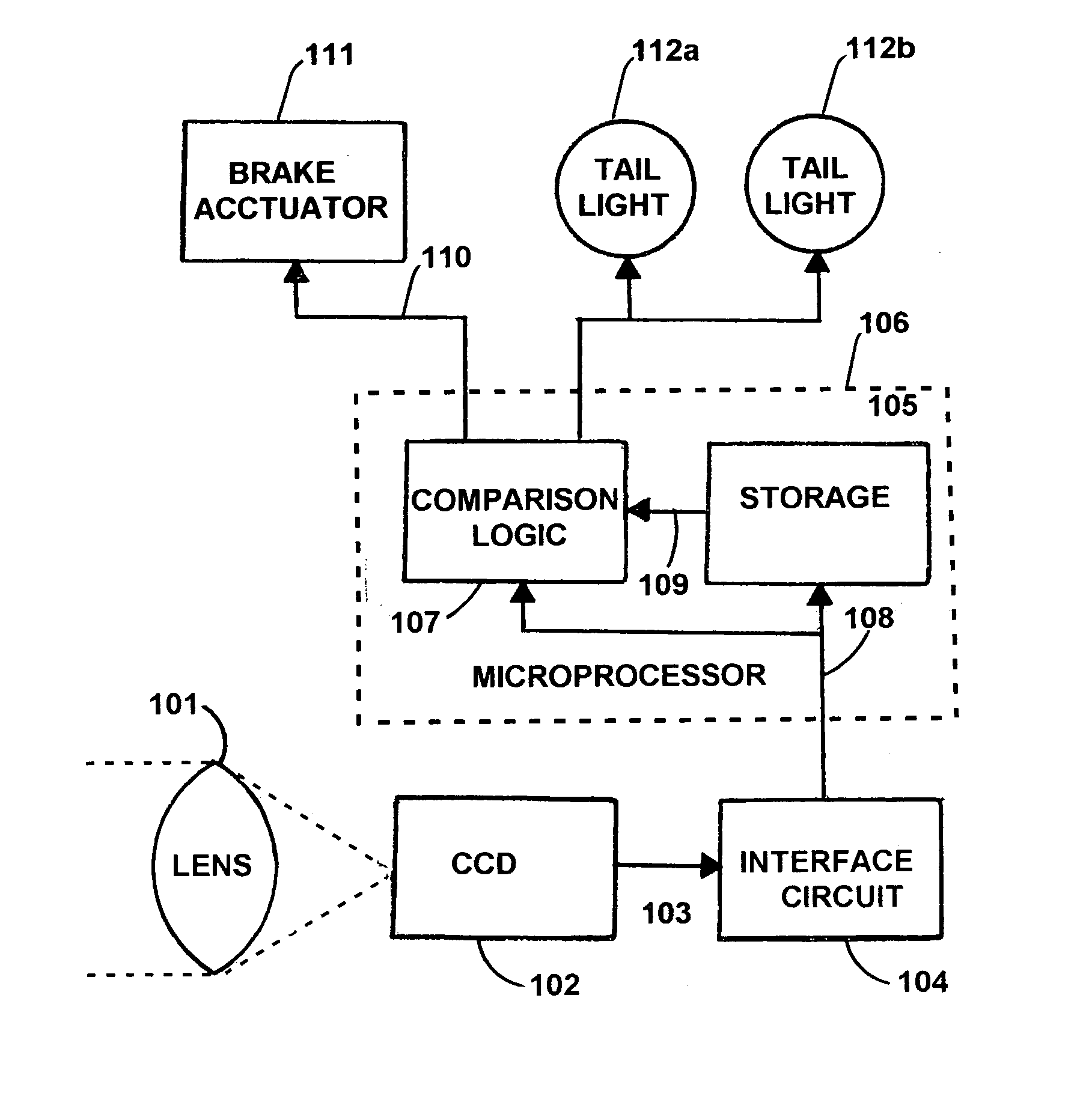
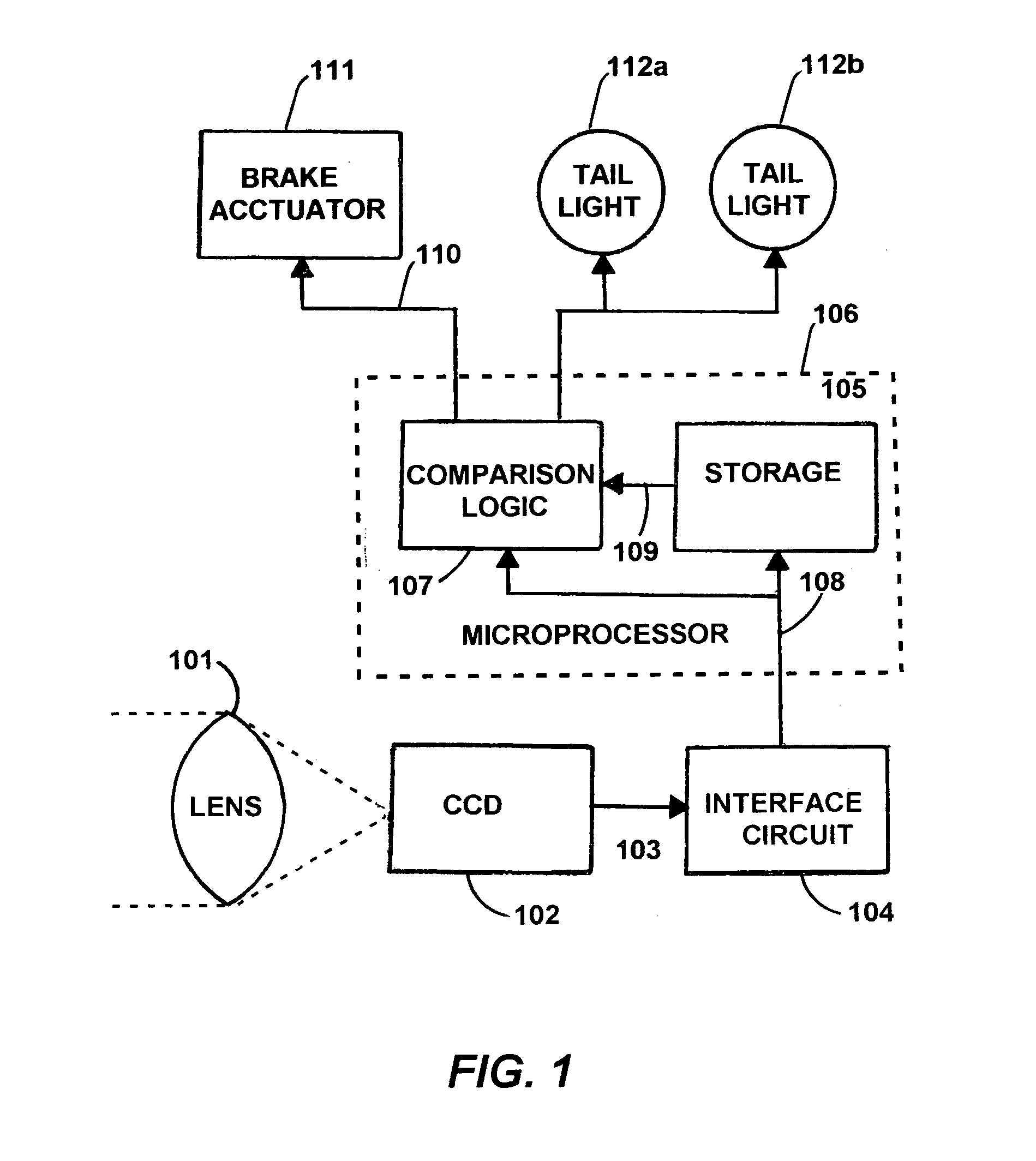
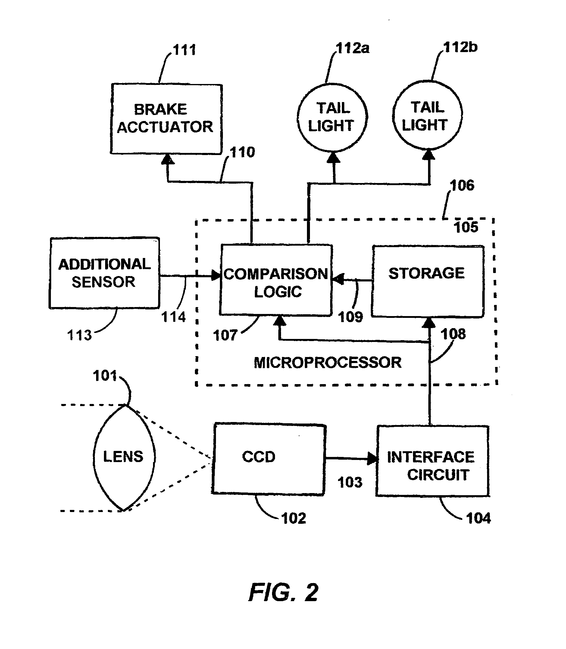
[0077]A fourth preferred embodiment may be block diagrammed (not shown) equivalently to any of the above preferred embodiments one through three, excepting only that the color CCD sensor (standard red-green-blue device) 102 shown in FIGS. 1 and 2 is replaced with a sensor wherein the sensed wavelengths (colors) are modified so that at least one of the wavelengths is well into the infrared. Such an infrared sensor is capable of sensing hot tailpipes, even during bad visibility conditions as are due to, most commonly, fog. Moreover, the logic of detection is modified so as to consider the intensity of warm or hot objects ahead, and the rate of change of such intensity. This information, possibly coupled with taillight data and / or radar proximity data, is used to form a more accurate estimate of what vehicles are ahead, and what the closure rate to these vehicles might be.

fifth embodiment

9. a Vehicle Brake Light Sensing and Control System

[0078]A fifth preferred embodiment of the present invention is similar to any of the above preferred embodiments, except that instead of using just a single CCD optical sensor, two such sensors are used in a stereoscopic mode. Differences between what each of the two sensors detects are considered in developing such 3-dimensional information as provides both (i) estimated distance, and (ii) rates of change in estimated distance, to objects ahead of the subject vehicle. Because the separation of two separate sensors provides a wider baseline over which trigonometric calculations of distance may be made, the two separate sensor system delivers enhanced ranging accuracy. Such range information may be used singly, or in concert with any of the other types of information developed for any of the preferred embodiments.

sixth embodiment

10. a Vehicle Brake Light Sensing and Control System

[0079]A sixth preferred embodiment of the present invention is similar to any of the above preferred embodiments, except that instead of, or in addition to, the brake activation and / or taillight activation outputs, a driver alert indication or warning is activated, this serving as either a visual and / or an audio alarm or indication. For example, at a first threshold of the aforesaid “points” as do indicate a likelihood of collision, an alarm warning, which is preferably audible, is sounded. This audio alarm might be of a constant intensity or pitch, or of an intensity or pitch varying with the estimated time to impact. At a second threshold, the vehicle's taillights are activated. At a third threshold, the vehicle's brakes are activated. These various thresholds may be identical or different in magnitude.

11. A Seventh, Hybrid, Embodiment of a Digital Vehicle Brake Light Sensing and Control System with (i) Analog Sensing and (ii) Di...


PUM


Abstract

Any presence of brake light emissions of another vehicle to the forward of a subject vehicle is sensed in a color camera and microprocessor system that detects (i) red light(s) illuminations in excess of other colors, that are any of (ii) appropriately sized, (iii) appropriately located, (iv) simultaneously occurring, (v) spaced apart in separation, (vi) substantially horizontal, and/or (vii) of approximately of equal intensity, as would be appropriate to a single brake light, or to a pair of brake lights, as the case may be. The brake lights of the subject vehicle are preferably applied either during (i) the persistence of any detection of the brake light(s) of any other vehicle(s) to the forward, or (ii) normal application of the subject vehicle's own brakes. The forward-sensed rearward-propagated brake light signal is preferably delayed in propagation, limiting any propagation of minor perturbations in traffic. Optional application of the vehicle's own brakes may be conditioned upon (i) proximity to and/or rate of closure with a forward emission source as is preferably determined by angles, and/or upon (ii) rate of closure, speed or deceleration G force of the subject vehicle. The brake light signal, whether simple or sophisticated in either its development and/or presentation, beneficially alerts drivers to the rear of impending or actual slowing, thus deterring rear end collisions and promoting fuel economy.

Description

BACKGROUND OF THE INVENTION[0001]1. Field of the Invention[0002]The present invention generally concerns vehicular safety, including control of a vehicle's brakes and / or brake lights.[0003]The present invention particularly concerns a (i) camera- and (ii) microprocessor-based system for sensing and interpreting brake lights to the forward of a subject vehicle.[0004]The present invention further particularly concerns the criteria relevant to the sensing of (i) brake lights to the forward of a subject vehicle, and also (ii) the distance(s) of separation, and (iii) the rate(s) of change in this (these) distance(s) of separation.[0005]The present invention still further particularly concerns the appropriate combination of sensed conditions, including such sensed conditions as may each have some degree of uncertainty, as will desirably occasion activation of the brake lights and / or brakes of the subject vehicle.[0006]The present invention yet still further particularly concerns (i) the i...

Claims


Application Information

Patent Timeline
IPC IPC(8): H04N7/18
CPCB60Q1/44G06K9/00825G06K9/00805G06V20/58G06V20/584
Inventor MAGER, DONALD
Owner BRAKE
Why Eureka
Try Eureka