Auto-adjusting system for an optical incident angle

a technology of auto-adjusting system and optical incident angle, which is applied in the direction of digital signal error detection/correction, instruments, recording signal processing, etc., can solve the problems of insufficient automatic the inability to maintain the recording/reproducing quality of optical information, and the inability to maintain the focus distance between the pickup head and the compact disc. to maintain a consistent quality

Inactive Publication Date: 2008-04-29
MEDIATEK INC
View PDF24 Cites 3 Cited by
  • Summary
  • Abstract
  • Description
  • Claims
  • Application Information

AI Technical Summary

Benefits of technology

[0015]The objective of the present invention is to provide an auto-adjusting system for an optical incident angle applied in an optical information recording / reproducing apparatus, which is used for correcting the inclination of the pickup head on line, so that the laser beam can be kept in a predetermined optical incident angle to read data from the compact disc, and thus maintaining the optical information recording / reproducing quality.
[0019]Compared with the prior art, the optical information recording / reproducing apparatus doesn't need to install a tilt sensor; it obtains the tilt of the optical incident angle from the laser beam to the compact disc as in the prior art, which utilizes the focus output voltage to keep a focus distance between the pickup head and the compact disc. After calculating and obtaining the tilt of the optical incident angle, the auto-adjusting system for an optical incident angle of the present invention further actuates the inclination of the pickup head, so that the laser beam is parallel to the normal direction of the selected recording block, thus achieving the objective of auto-adjusting for an optical incident angle. Therefore, the optical information recording / reproducing apparatus, which utilizes the auto-adjusting system for an optical incident angle of the present invention, not only can maintain the optical information recording / reproducing quality but is also acceptable under the consideration of cost when producing the optical information recording / reproducing apparatus.

Problems solved by technology

However, how to maintain the optical information recording / reproducing quality is always the problem that needs to be overcome.
There are many reasons why the pickup head cannot maintain a focus distance with the compact disc; for example, the compact disc is not smooth, or the compact disc wobbles or is deformed while rotating.
However, as the wavelength of laser beam reduces and the rotation speed of compact disc increases, only maintaining the focus distance between the pickup head and the compact disc automatically is still not enough to keep a consistent quality for the optical information recording / reproducing system.
The reason that leads to the above disadvantages of the prior art is due to the fact that the laser beam cannot be orthogonal to the compact disc while the laser beam is focused on the compact disc.
In other words, although the technology of focus servo enables the pickup head to maintain the focus distance with the compact disc, whether the laser beam is orthogonal to the compact disc cannot be guaranteed.
However, as shown in FIG. 2, the prior art cannot detect and adjust an inclination θ1 resulted from the laser beam that is not orthogonal.
This disadvantage causes lower signal quality while reading or recording the optical information.
However, the installation of the tilt sensor will increase the cost of production.

Method used


Image

  • Auto-adjusting system for an optical incident angle
  • Auto-adjusting system for an optical incident angle
  • Auto-adjusting system for an optical incident angle

Examples


Embodiment Construction

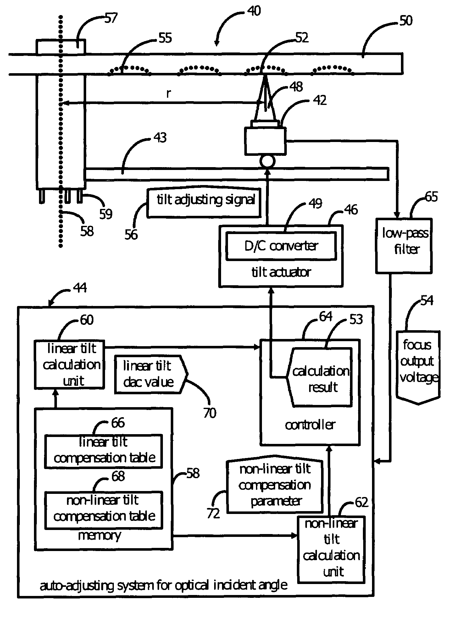
[0029]The present invention provides an auto-adjusting system for an optical incident angle in an optical information recording / reproducing apparatus. The optical information recording / reproducing apparatus of the present invention is able to do away with the use of the tilt sensor of the prior art and can still obtain the optical incident angle to auto-adjust the pickup head, so as to substantially keep the pickup head with the compact disc at the orthogonal position of 90 degree.

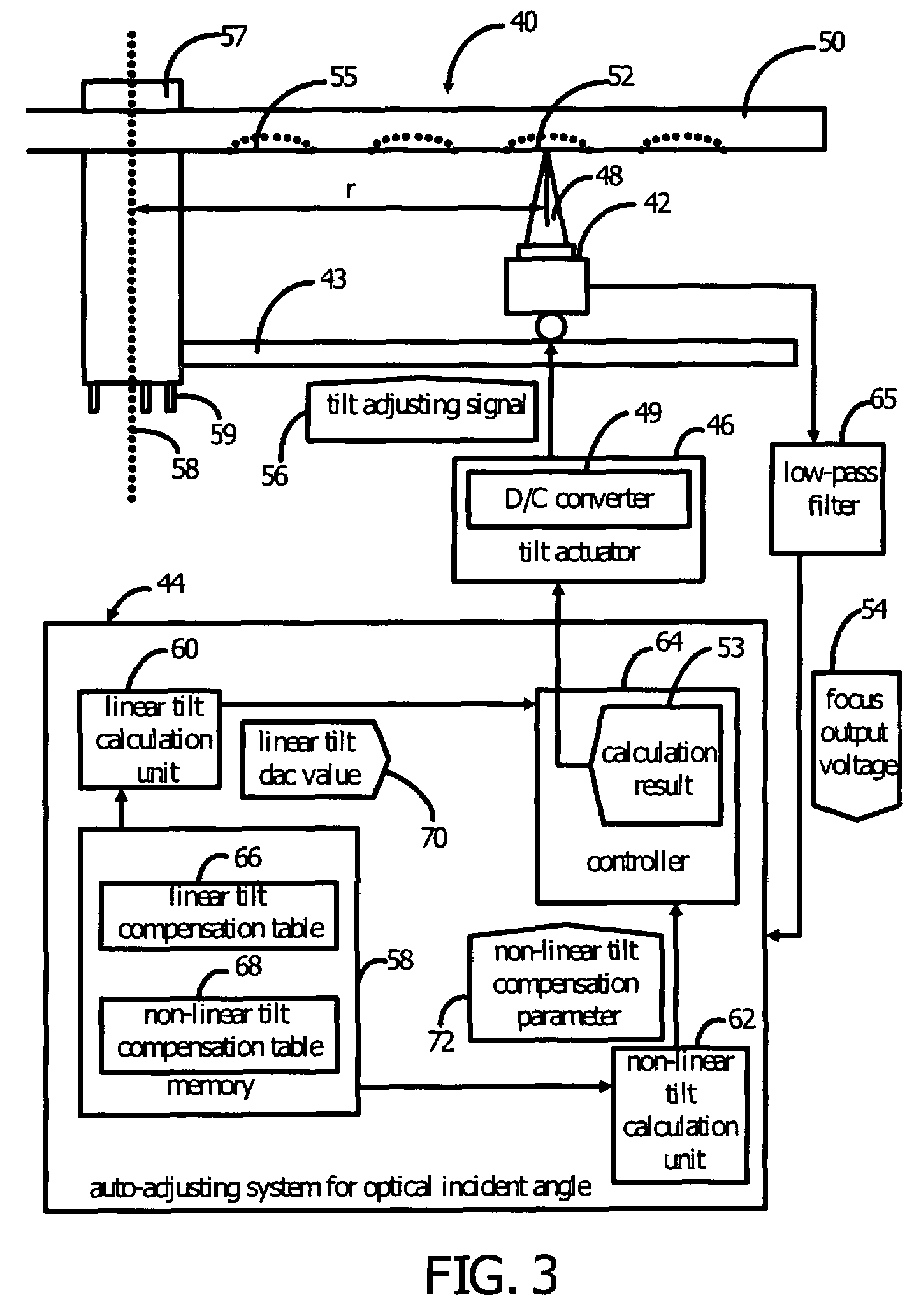
[0030]Please refer to FIG. 3. FIG. 3 is a schematic diagram of an optical information recording / reproducing apparatus 40 according to the present invention. The optical information recording / reproducing apparatus 40 comprises a pickup head 42, a pickup head guiding track 43, an auto-adjusting system 44 for an optical incident angle, and a tilt actuator 46. The pickup head 42 generates a laser beam 48 to read data from a recording block 52 of a first radius r on a compact disc 50 and receives a focus output...


PUM

PropertyMeasurementUnit
optical incident angleaaaaaaaaaa
wavelengthsaaaaaaaaaa

Abstract

An auto-adjusting system for an optical incident angle comprises a memory, a linear tilt calculation unit, a non-linear tilt calculation unit, a controller, and a tilt actuator. The memory is used for storing a linear tilt compensation table and a non-linear tilt compensation table. The linear tilt calculation unit is used for calculating the corresponding linear tilt dac value by consulting the linear tilt compensation table according to a first radius and a focus output voltage. According to a predetermined comparison procedure, the non-linear tilt calculation unit is used for generating a second radius wherein the compact disc begins to generate non-linear deformation and then obtaining the corresponding non-linear tilt compensation parameter by consulting the non-linear tilt compensation table according to the first radius and the second radius. The controller is used for controlling the pickup head, the memory, the linear tilt calculation unit, and the non-linear tilt calculation unit.

Description

BACKGROUND OF THE INVENTION[0001]1. Field of the Invention[0002]The present invention relates to an auto-adjusting system for an optical incident angle, especially to an auto-adjusting system for an optical incident angle applied in an optical information recording / reproducing apparatus, which is used for correcting the inclination of the pickup head on line, so that the laser beam can be kept in a predetermined optical incident angle to read data from the compact disc.[0003]2. Description of the Prior Art[0004]This era is the time of information explosion. As the amount of data increases quickly, the technology of information storage and process is also improving rapidly. The technology of optical information storage is quite important in the related field.[0005]In order to improve the technology of information storage and increase the amount of information storage, the relative technology of optical information recording / reproducing apparatus is developed mainly by speeding up the...

Claims


Application Information

Patent Timeline
Patent Type & Authority Patents(United States)
IPC IPC(8): G11B7/00
CPCG11B7/0956
Inventor KUN-YI, CHAN
Owner MEDIATEK INC
Why Eureka
Try Eureka