
Method and device for liner system

a liner system and liner technology, applied in the field of deepwater exploration drilling equipment, can solve the problems of significant weight and size of the floating drilling vessel, requiring a relatively costly drilling vessel to be used, and the size and weight of the marine drilling riser, so as to reduce the needed diameter of the drilling riser and low cost

Active Publication Date: 2008-05-06
ENHANCED DRILLING
View PDF16 Cites 58 Cited by
  • Summary
  • Abstract
  • Description
  • Claims
  • Application Information

AI Technical Summary

Benefits of technology

[0007]The main objective of the present invention is to reduce the needed diameter of the drilling riser. This is achieved by pre-positioning one or more liners below the substantial part of the drilling riser, preferably inside the surface casing, and drill the holes for these liners using underreamers after the BOP and marine drilling riser have been installed. This would allow a very small diameter riser to be used, and thus allow a low cost drilling vessel to be used. Preferably a set of telescopic liners are installed below the well head.
[0009]Deep water slim hole exploration drilling using a telescopic liner system according to the present invention allows the size of the wellhead, BOP and the marine drilling riser to be reduced significantly compared to conventional 18¾″ wellhead systems. The proposed system is preferably based on using a 10¾″ marine drilling riser, a 9½″ BOP and a 9½″ wellhead. The system may also be termed a 9½″ wellhead system.
[0010]According to a preferred embodiment of the invention, after the conductor casing and surface casing have been run and cemented, only liners may be used to complete the well. Consequently, no shoulder in the wellhead will be required for casing suspension. Only an arrangement for supporting the test string during well testing will be accommodated for. This eliminates time consuming operations for running and retrieving wear bushings.

Problems solved by technology

A limited application of this technique has been used in offshore applications from a floating vessel.
One of the main limitations when drilling in deep waters from floating drilling vessels is the size and the weight of the marine drilling riser.
However, due to the close distance between the pore pressure curve and the fracturing curve, relatively many casing points are normally required to reach the reservoir section.
So, even with conventional slim hole drilling, the weight and the size of the marine drilling riser will be significant and require a relatively costly drilling vessel to be used.
The problem of applying slim hole drilling on deep wells is that there is a limit on how long each section of casing reasonably can be.
This puts a limitation on how deep wells that can be drilled using this technique.

Method used


Image

  • Method and device for liner system
  • Method and device for liner system
  • Method and device for liner system

Examples


Embodiment Construction

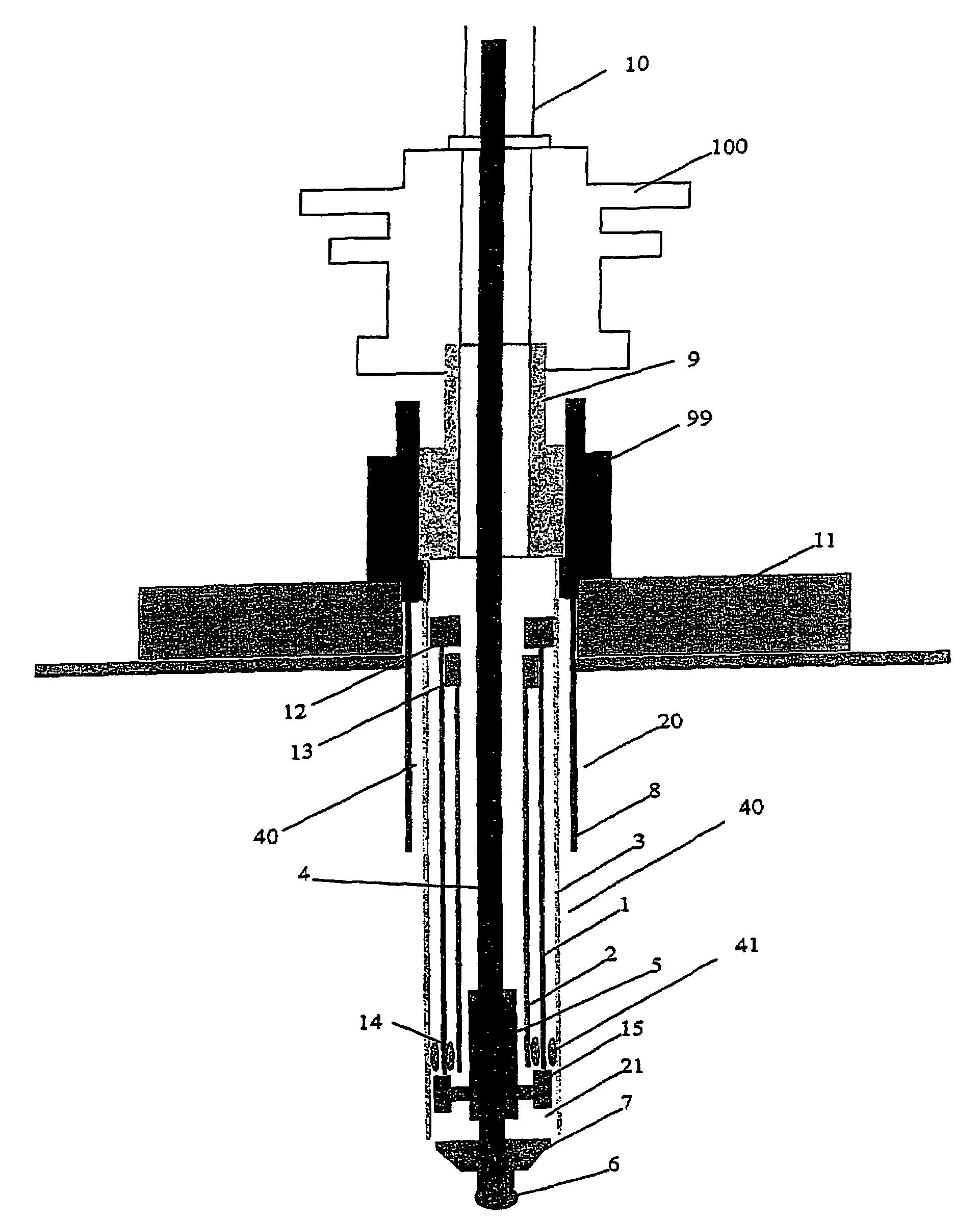
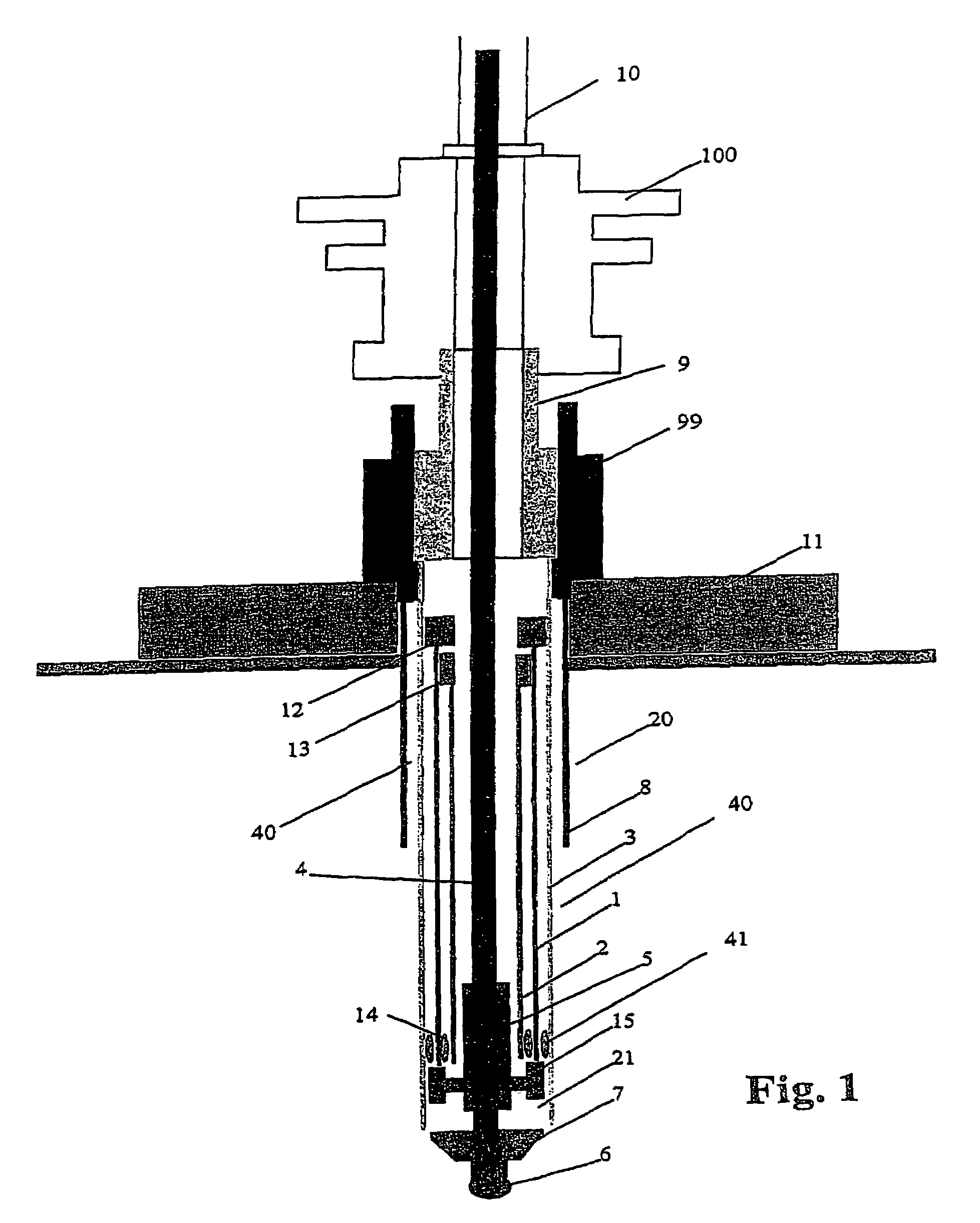
[0020]FIG. 1 illustrates the concept of a satellite well with a pre-positioned telescopic liner system according to present invention based on using a set of pre-positioned liners consisting of a 11¾″ liner 1 and a 9⅝″ liner 2 inside a 14″ surface casing 3 connected to the wellhead 9. A 5″ drill string 4 with a mud motor 5, a bit 6 and an underreamer 7 is used.

[0021]In a first step a temporary guidebase 11 is installed and a bore hole 20 is drilled or jetted down to about 100 m BML (below mud line) in a conventional way without using a drilling riser and BOP. An 18⅝ conductor casing 8 with a conductor housing 99 attached on top is then installed in the borehole 20.

[0022]Then the next hole section 40 is normally also drilled without BOP and drilling riser.

[0023]After this a unit comprising a well head 9, the 14″ surface casing 3, and a set of the telescopic liners 1, 2 is installed.

[0024]The well head 9 connected to the surface casing 3 with the pre-positioned liners 1, 2 suspended i...


PUM


Abstract

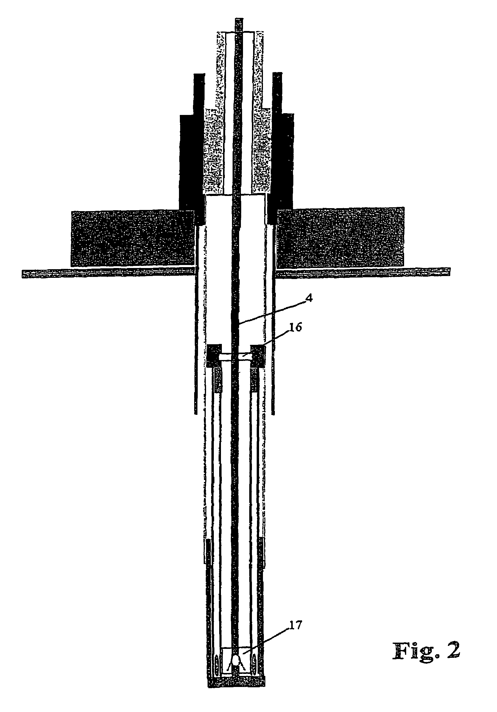
Method for drilling and lining a well wherein at least one liner (1, 2, 32) with a larger external diameter than the substantial part of a drilling riser (10) is pre-installed at a point below the substantial part of the drilling riser (10). A bore hole section (21) is drilled after the drilling riser (10) has been installed, the bore hole section having a larger diameter than the at least one pre-installed liner (1, 2, 32). The at least one pre-installed liner (1, 2, 32) is subsequently lowered into the bore hole section (21, 22). A drilling and liner system for implementing the method is also described.

Description

RELATED APPLICATIONS[0001]This application is a National Stage of International Application No. PCT / NO03 / 00077, filed 06 Mar. 2003, which published in the English language and is an international filing of Norway Application No. 2002 1179, filed 08 Mar. 2002. Priority is claimed. Each of these applications is herein incorporated in its entirety by reference.FIELD OF THE INVENTION[0002]The present invention relates to deep-water exploration drilling equipment, and more particular to a liner system according to the preamble of the appended claim 1.BACKGROUND OF INVENTION[0003]A slim well is highly desirable since it reduces the costs for drilling and completion substantially. Such a well should be designed with the smallest possible diameter needed. Slim hole drilling has been used onshore for a long time. A limited application of this technique has been used in offshore applications from a floating vessel. Slim hole drilling offers a significant potential in reduction of drill cuttin...

Claims


Application Information

Patent Timeline
IPC IPC(8): E21B7/128E21B15/02E21B33/043
CPCE21B33/043
Inventor SANGESLAND, SIGBJORN
Owner ENHANCED DRILLING
Learn More