Variable helix rotary cutting tool

a cutting tool and variable helix technology, applied in the field of rotary cutting tools and end mills, can solve the problems of end mill cutters breaking during use, internal stresses generated in end mill cutters during use, dull cutting edges of end mill cutters, etc., to reduce harmonic vibration, reduce wear, and improve life

Active Publication Date: 2008-05-06
CARBIDE GRINDING CO INC +1
View PDF26 Cites 41 Cited by
  • Summary
  • Abstract
  • Description
  • Claims
  • Application Information

AI Technical Summary

Benefits of technology

[0023]A further objective is to provide a rotary cutting tool that has reduced harmonic vibrations, a reduced rate of wear, and an increased life.

Problems solved by technology

Over time, the cutting edges of an end mill cutter become dull due to physical contact between the end mill cutter and workpieces.
As the cutting edges become dull, internal stresses generated within the end mill cutter during use increase.
It is common for end mill cutters to break during use due to the internal stresses.

Method used


Image

  • Variable helix rotary cutting tool
  • Variable helix rotary cutting tool

Examples


Embodiment Construction

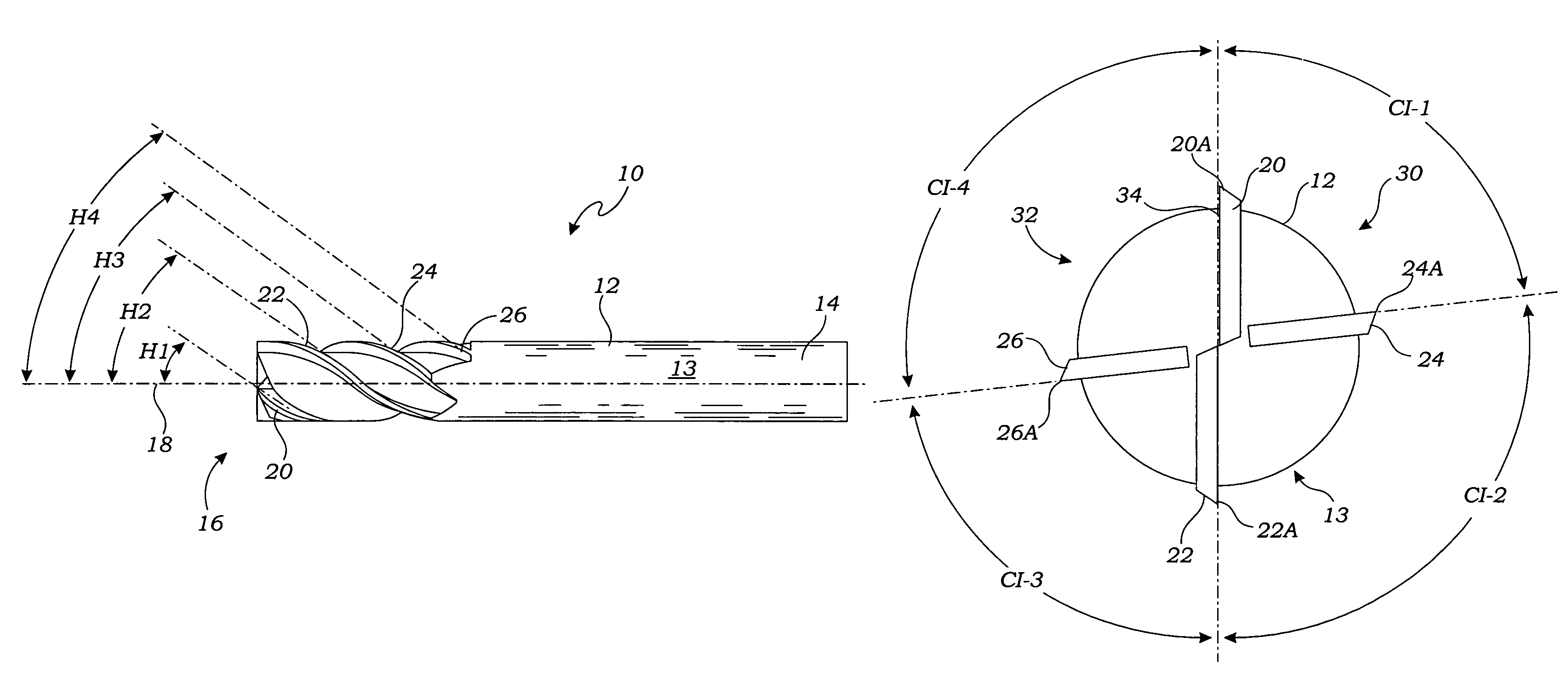
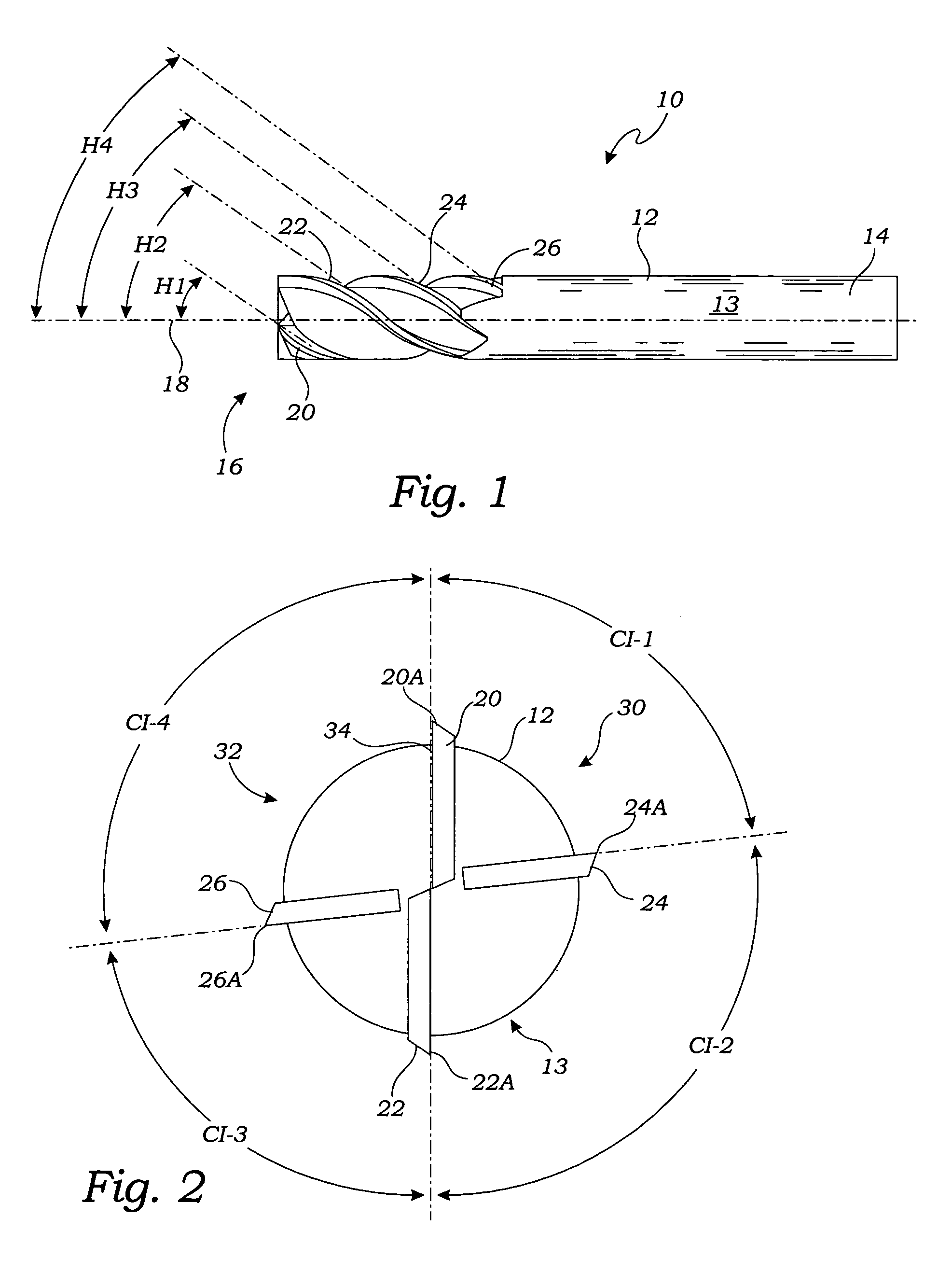
[0028]FIG. 1 is a side elevation view of one embodiment of a rotary cutting tool 10 including a substantially cylindrical main body 12 having a shank end 14 at one end and a cutting end 16 formed integrally opposite the shank end 14. The main body 12 having a longitudinal axis of rotation 18. In the embodiment of FIG. 1, the rotary cutting tool 10 is an end milling cutter or “end mill,” and has a pair of flutes 20 and 22 comprising a first flute 20 and a second flute 22, interleaved with a third flute 24 and a fourth flute 26 about an outer surface 13 of the main body 12. That is, members of the pairs of flutes 20 and 22 alternate with either the third flute 24 or fourth flute 26 about the outer surface 13 of the main body 12.

[0029]As shown in FIGS. 1 and 2, the pair of flutes 20 and 22 are formed on opposite sides of the main body 12, and each of the pair of flutes 20 and 22 extends continuously from the cutting end 16 towards the shank end 14. Each of the pair of flutes 20 and 22 ...


PUM


Abstract

A rotary cutting tool has a substantially cylindrical main body and four flutes. The main body has a shank end, a cutting end formed integrally opposite the shank end, and a longitudinal axis of rotation. The four flutes include a pair of flutes comprising a first flute and a second flute formed on opposite sides of the main body, and each of the pair of flutes are symmetrical and have the same helix angle. A third flute is formed on one side of the main body between the pair of flutes, and defines a helical cutting edge having a helix angle that is different than the helix angle of the pair of flutes. A fourth flute is formed on the other side of the main body, and defines a helical cutting edge having a helix angle that is different than the helix angle of the pair of flutes and different than the helix angle of the third flute.

Description

CROSS-REFERENCE TO RELATED APPLICATIONS[0001]Not ApplicableSTATEMENT REGARDING FEDERALLY SPONSORED RESEARCH[0002]Not ApplicableBACKGROUND OF THE INVENTION[0003]1. Field of the Invention[0004]This invention relates generally to rotary cutting tools and end mills, and more particularly to helically fluted end mills having variable helical angles for improved performance characteristics.[0005]2. Description of Related Art[0006]Rotary cutting tools are used for various machining operations on workpieces. An end mill cutter or “end mill” is a type of rotary cutting tool. Machine operations often carried out using an end mill cutter include the forming of slots, keyways, and pockets. During typical use of an end mill cutter, a milling machine rotatably drives the end mill cutter about its longitudinal axis, and various cutting edges of the end mill cutter are used to remove material from a workpiece.[0007]Over time, the cutting edges of an end mill cutter become dull due to physical conta...

Claims


Application Information

Patent Timeline
Patent Type & Authority Patents(United States)
IPC IPC(8): B23C5/10
CPCB23C5/10B23C2210/0485B23C2210/0492B23C2210/203Y10T407/1966Y10T407/1962Y10T407/196Y10T407/1958B23C2210/282
Inventor GREENWOOD, MARK L.CRANKER, KEVIN J.
Owner CARBIDE GRINDING CO INC
Why Eureka
Try Eureka