Modular fluid distribution system

a fluid distribution system and module technology, applied in valve housings, couplings, transportation and packaging, etc., can solve the problems of high labor intensity, high labor intensity, and large number of fittings and pipe sections, and achieve low labor requirements

Inactive Publication Date: 2008-05-13
DOYLE MICHAEL
View PDF20 Cites 30 Cited by
  • Summary
  • Abstract
  • Description
  • Claims
  • Application Information

AI Technical Summary

Benefits of technology

[0019]and wherein the retaining pins means preventing substantial disengagement of the cylindrical flow element from the cylindrical cavity, the retaining pins preventing substantial transmission of torque between the first mounting block and the second mounting block;
[0026]An additional benefit of the retaining means is the minimization of transferred torque from one part of a modular fluid distribution system to another. The cylindrical flow element is not substantially prevented from axially rotating about the axis of the cylinder. Therefore, torque cannot be transmitted through the connection to a significant degree.
[0035]Additionally, if one or more of the cylindrical cavities were not needed in an application, a plugging means may be employed. The cylindrical flow element having retaining grooves formed at a first terminus; the fluid passage being excluded, preventing substantial flow of fluid when installed in the cylindrical cavity.
[0036]The present invention relates to a modular architectural approach and its implementation to provide a system for enabling the sampling, conditioning, control, and distribution of fluids utilizing a standardized set of mounting blocks and interconnecting tubular elements, requiring no welds. It allows the design, assembly, installation, and maintenance of fluid control systems to be relatively inexpensive when compared to the conventional method of welding components together using metal piping.
[0038]The invention emphasizes simplicity by covering a great majority of the requirements with as little as two types of mounting blocks and three cylindrical flow elements, while the general architecture allows for complexity as needed in the form of second level interconnection, custom interconnect elements for fluid inlet and outlet from the system, and mounting block variations in the number of lateral face connections and fluid routing options. The simplicity of the mounting block in the current modular approach allows complex systems to be designed and rapidly built without welding, specialized tools, or custom processes. Labor requirements are low in terms of specialized capability and complexity of task with minimum possibility of error.

Problems solved by technology

Those skilled in the art recognize a number of problems associated with prior art gas sticks of the type illustrated in FIG. 1.
The assembly of these components can be relatively labor intensive.
Similarly, the disassembly of these components for repair or replacement can be labor-intensive and costly.
Another problem associated with fluid control assembly is that the numerous fittings and pipe sections produce a relatively long and heavy device.
The attachment of the fluid control assembly to a substrate also produces problems since the entire fluid assembly must be removed from the substrate in order to repair the gas stick.
This increases the amount of in-house stock required for daily operation, resulting in higher operation costs and an increase in the complexity of the assembled system.
Another problem experienced with existing systems is the inability to purge individual components and fluid passages without purging the surrounding components and fluid passages.
Additionally, when face seal or compression-type fittings are utilized to connect the various fluid control components, undesirable torque can be transmitted throughout the gas stick.
The operator can “chase” a leak in the gas stick by tightening one fitting, only to find that the resulting torque has loosened another fitting, causing it to leak.
This process is lengthy and often ineffective.

Method used


Image

  • Modular fluid distribution system
  • Modular fluid distribution system
  • Modular fluid distribution system

Examples


Embodiment Construction

[0052]The detailed description set forth below in connection with the appended drawings is intended as a description of presently-preferred embodiments of the invention and is not intended to represent the only forms in which the present invention may be constructed and / or utilized. The description sets forth the functions and the sequence of steps for constructing and operating the invention in connection with the illustrated embodiments. However, it is to be understood that the same or equivalent functions and sequences may be accomplished by different embodiments that are also intended to be encompassed within the spirit and scope of the invention.

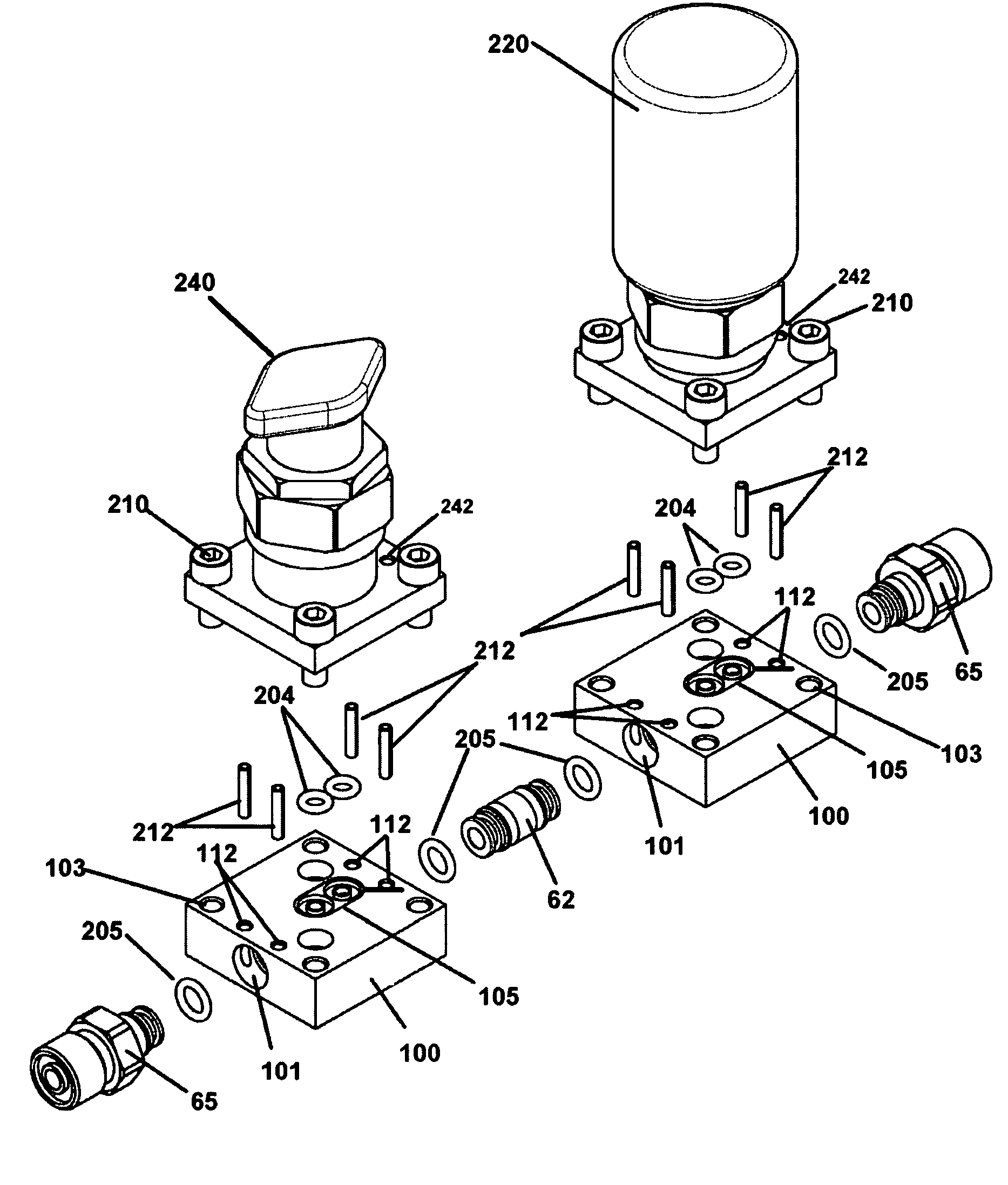
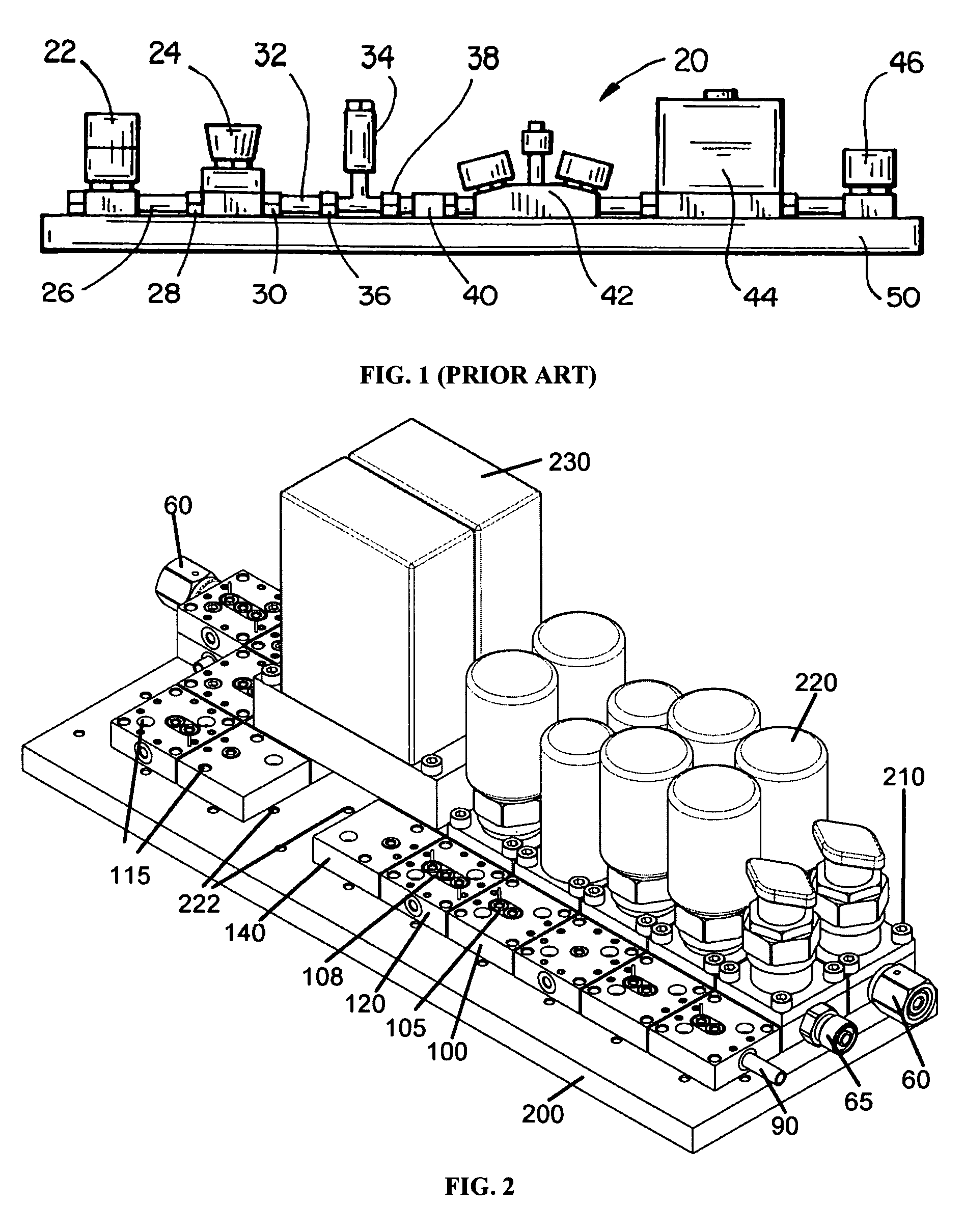
[0053]FIG. 2 depicts a fluid control system composed of three linear arrays of blocks or “sticks” of components. The term “stick” is a term of art describing a linear array of fluid components sequentially interconnected performing a specific function as a whole, such as conditioning and controlling the amount of fluid to be delivered. ...


PUM


Abstract

An interconnection assembly for the transport of a fluid between an external fluidic means and a mounting block of a modular fluid distribution system, comprising: a cylindrical cavity formed through a face of the mounting block; a cylindrical flow element, a fluid passage formed therethrough, at least one retaining groove being formed on the outer surface; a retaining means; wherein the cylindrical flow element is inserted into the cylindrical cavity, the annular sealing means being compressed, the annular sealing means forming a hermetic seal between the fluid passage and the fluid port, the retaining means engaging retaining groove, the retaining means being braced against the mounting block; and wherein said fluid is transported between said external fluidic component and said mounting block via said cylindrical flow element.

Description

CROSS-REFERENCE TO RELATED APPLICATIONS[0001]This application is entitled to the benefit of Provisional Application for Patent Ser. No. 60 / 546,612 filed on Feb. 20, 2004.BACKGROUND OF THE INVENTION[0002]This invention relates generally to fluid control systems. More particularly, this invention relates to a modular mounting system for chemical fluid control components of a chemical fluid control system.[0003]Fluid control components are used to control the delivery of a fluid (i.e., a gas or liquid) in industrial processes. These components are arranged so that fluid is carried through each of the components. Chemical delivery systems are used in numerous industries to control the flow of fluids, including gas reactants and other chemicals (e.g., liquids). In general, process control of fluid production requires the selection, conditioning, and metering of specific fluids, which are then routed to analytical equipment. The fluid control system is known as a sampling system, reflecti...

Claims


Application Information

Patent Timeline
Patent Type & Authority Patents(United States)
IPC IPC(8): F16K11/10
CPCF15B13/0817F15B13/0832F15B13/0892F15B13/0896F16K27/003Y10T137/87885
Inventor DOYLE, MICHAEL
Owner DOYLE MICHAEL
Why Eureka
Try Eureka