
Device for the immobilization of nano- and micro-sized particles in a solid-fluid contact vessel facilitating mass-momentum, and heat-transport at the solid-fluid interfaces

a technology of nano- and micro-sized particles and contact vessels, which is applied in the direction of electrostatic separation, chemical/physical/physicochemical processes, energy-based chemical/physical/physical processes, etc., can solve the problems of reducing the effect of immobilization technique, reducing the practicality of immobilization technique types, and reducing the effect of type (2)

Inactive Publication Date: 2008-05-13
CROSS KENNETH
View PDF2 Cites 5 Cited by
  • Summary
  • Abstract
  • Description
  • Claims
  • Application Information

AI Technical Summary

Benefits of technology

"This patent describes a new way to hold small chemical catalyst particles in place within a reactor. The method involves using a special reactor design and a high-surface-area, high-magnetic-permeability material called HPMM. The HPMM is placed within the reactor and acts as a magnetic field concentrator, with the only portion of the magnetic circuit that is open for work also being the chemical reaction zone. The HPMM is packed with many long intertwined fibers, and the magnetic lines of flux are directed preferentially through these fibers. The strength of the magnetic field decreases quickly at the surface of each fiber, resulting in a very high magnetic field gradient at the surface of each fiber. This high magnetic field gradient is what holds the nanoparticles in place within the reactor. The invention does not use any adhesives, electroplating, electrodeposition, impregnation, nanocages, or zeolytes to hold the catalyst particles in place. The reactor can be designed using either a permanent magnet or an electromagnet."

Problems solved by technology

Unfortunately, the minuscule size of nanoparticles, though having the advantages discussed above, also comes with an inherent disadvantage: it renders both of these immobilization technique types useless: Technique type (1) cannot fit enough nanoparticles in a small enough space to take advantage of the nanocatalysts' high surface area and always covers up a significant portion of the nanocatalyst particles' surfaces technique, further reducing its efficacy, while type (2) is impractical for any particles below about 1 mm, let alone nano-sized particles, especially considering requirements a, b, c, & d above.

Method used


Image

  • Device for the immobilization of nano- and micro-sized particles in a solid-fluid contact vessel facilitating mass-momentum, and heat-transport at the solid-fluid interfaces
  • Device for the immobilization of nano- and micro-sized particles in a solid-fluid contact vessel facilitating mass-momentum, and heat-transport at the solid-fluid interfaces
  • Device for the immobilization of nano- and micro-sized particles in a solid-fluid contact vessel facilitating mass-momentum, and heat-transport at the solid-fluid interfaces

Examples


Embodiment Construction

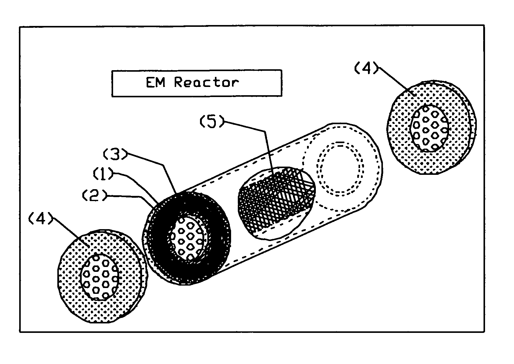
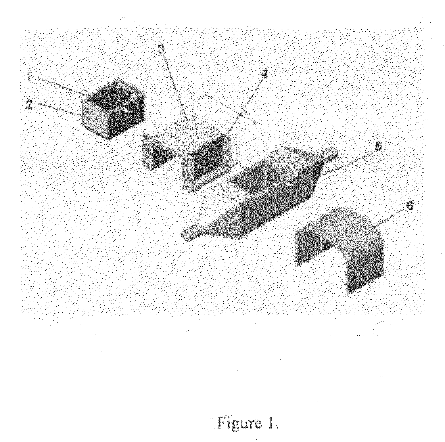
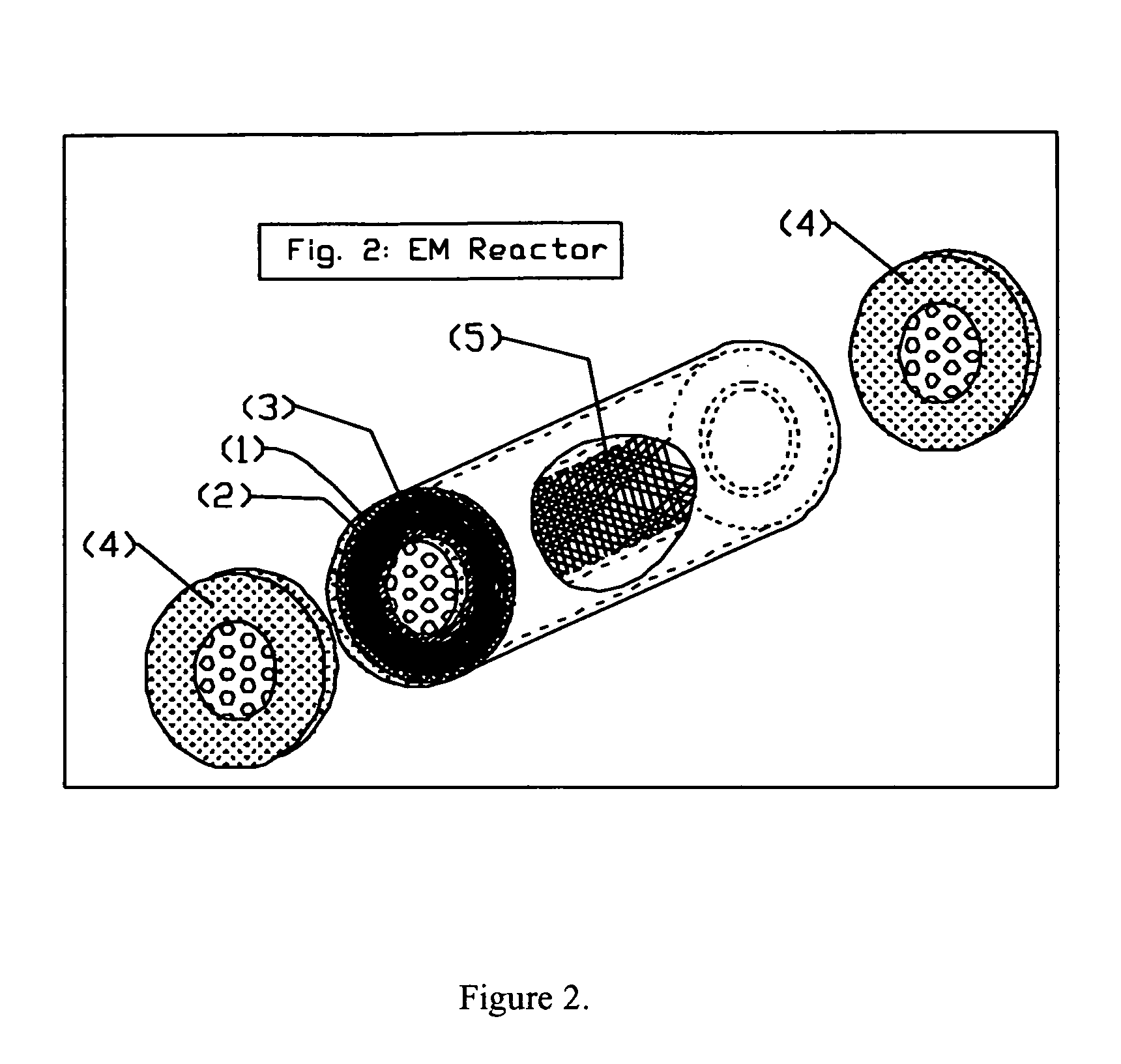
[0017]The preferred design of the PM reactor is depicted in FIG. 1. The high-permeability matrix (1) is loaded into the reactor basket (2), which is sealed into the reactor body using sealing lid (3). Two face-pole magnets (4) are then placed abreast of the main section of the reactor body (5) with their ‘North’ poles facing in the same direction. Note that, in this design, the lines of magnetic flux between the two inner facing poles of the magnet will be parallel and of nearly constant density within the boundary of the magnet faces. Note also that the area of each magnet pole-face (normal to the lines of flux) is approximately equal to the side face of the reactor basket. To increase the strength of the magnetic field between the two magnets, a metallic or otherwise high-magnetic permeability magnetic ‘bridge’ (6) can be lowered onto and over the outside of both magnets, creating, in effect, one ‘U’ shaped magnet with the ‘open’ section between the face-poles of the magnets. Henc...


PUM

PropertyMeasurementUnit
surface areaaaaaaaaaaa
diameteraaaaaaaaaa

Abstract

What is presented is an innovative design of a chemical reactor for catalytic breakdown of halogenated hydrocarbons, the body of which acts as a specialized electromagnet capable of immobilizing and retaining very large quantities of non-magnetized ferro- dia- or para-magnetic material-containing nano, micro-, or milli-particles within it's reactor volume despite high-velocity flow of any liquid through said reactor. This is accomplished without any pre-treatment to the nanoparticles, without the use of adhesive of any sort, electroplating, electrolytic action, nano-structured nanocages, membrane or other impregnation, or any other mechanical or chemical means.

Description

RELATED U.S. APPLICATIONS[0001]This application supplements and completes Provisional Application 60 / 658,383, filed Mar. 4, 2005.BACKGROUND OF THE INVENTION[0002]Metallic nanoparticles (MNPs), which have at least one compositional constituent which is ferromagnetic, diamagnetic, or paramagnetic, have several extremely interesting and useful properties: their size, their structure, and in the case of bi- or multi-metallic nanoparticles, their junction voltage(s). Because they range from approximately 10 nanometers to 3 millimeters in characteristic dimension, usually mean effective diameter, regardless of their exact nanostructure or shape, the resulting ratio of the surface area to the mass of these particles is very high: one kilogram of 10 mm diameter catalytic particles has a surface area of approximately 600 cm2, while the same mass of 10-nm diameter nanoparticles will have a surface area of approximately 600 million cm2, a six-order of magnitude ratio. In catalysis, the reactan...

Claims


Application Information

Patent Timeline
Patent Type & Authority Patents(United States)
IPC IPC(8): B01D35/06B03C1/02
CPCB01J8/06B01J19/087B01J2208/00814B01J2208/00884Y10S977/902
Inventor CROSS, KENNETH
Owner CROSS KENNETH
Learn More