Medium voltage heater element

a heater element and medium voltage technology, applied in the field of heater elements, can solve the problems of increasing the demands of the heat exchanger heater element, reducing the ability of the insulation powder to insulate, and so as to reduce the proximity of the connector pin

Active Publication Date: 2008-05-13
GAUMER
View PDF1 Cites 19 Cited by
  • Summary
  • Abstract
  • Description
  • Claims
  • Application Information

AI Technical Summary

Benefits of technology

[0009]In one embodiment, some of the heater elements protrude past the header plate at different distances to reduce the proximity of connector pins of the different elements to each other. Preferably, those at the closest distance are connected to one phase of a three-phase power source by a first conductor plate. The first conductor plate has holes through which the second phase and third phase heater elements protrude. A second conductor plate is connected to ends of the conductor pins of the second phase elements and has holes through which the third phase heater elements protrude. A third conductor plate is connected to ends of the conductor pins of the third phase heater elements. The second conductor plate is located between the first and third conductor plates. An insulation sleeve encases each tube of each of the second phase heater element and extends from the header plate through one of the holes in the first conductor plate. An insulation sleeve encases each tube of each of the third phase heater elements and extends from the header plate through one of the holes in the second conductor plate.

Problems solved by technology

Although considered a medium voltage for electrical power transmission in general, this voltage creates more demands on the heat exchanger heater elements.
While magnesium oxide provides excellent electrical insulation, it is a desiccant, thus it attracts moisture from the surrounding atmosphere.
The penetration of moisture reduces the ability of the insulation powder to insulate.
The higher voltage is more difficult to insulate, particularly at the exposed end face of the insulation powder, which is subject to moisture penetration.

Method used


Image

  • Medium voltage heater element
  • Medium voltage heater element
  • Medium voltage heater element

Examples


Embodiment Construction

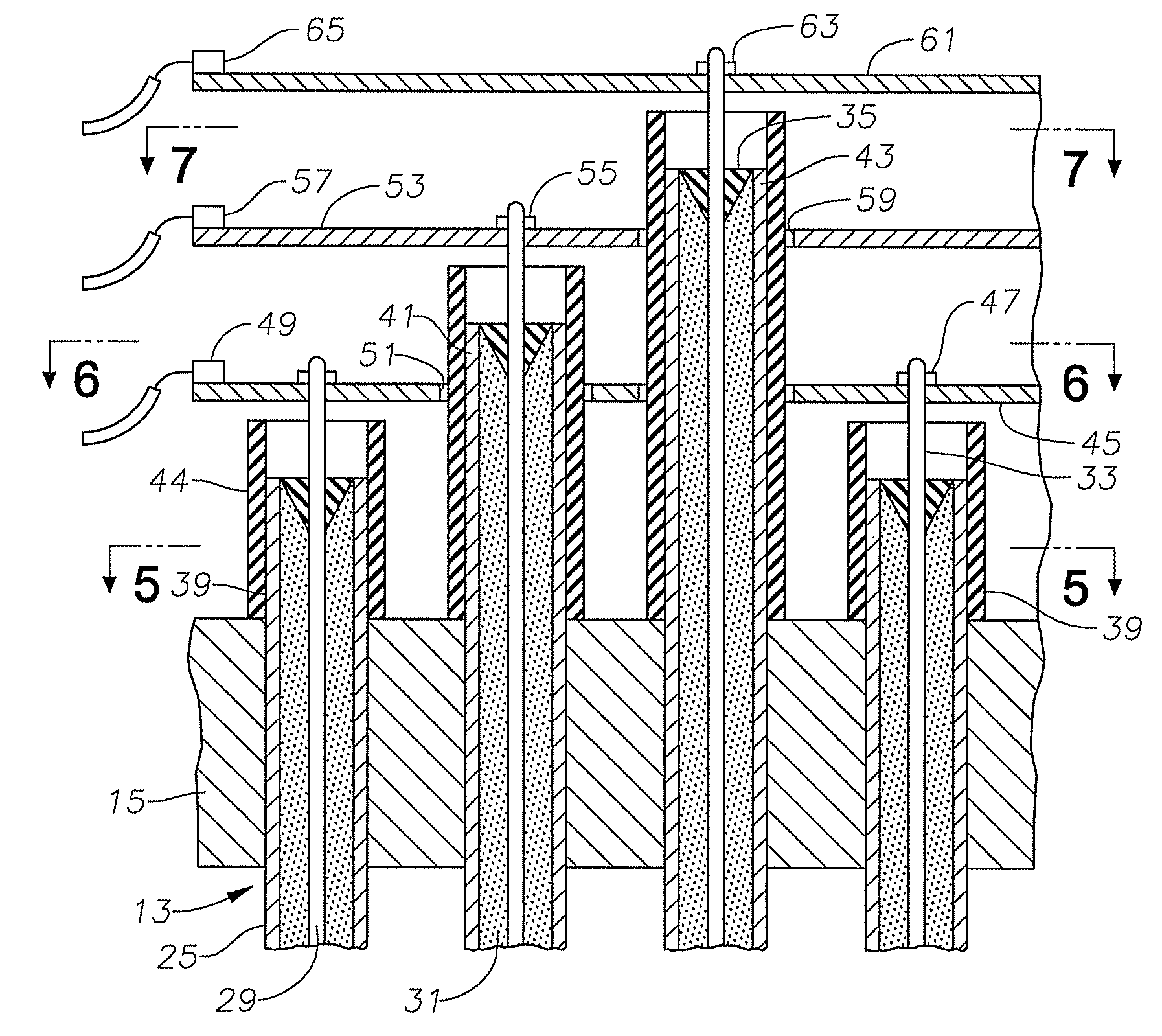
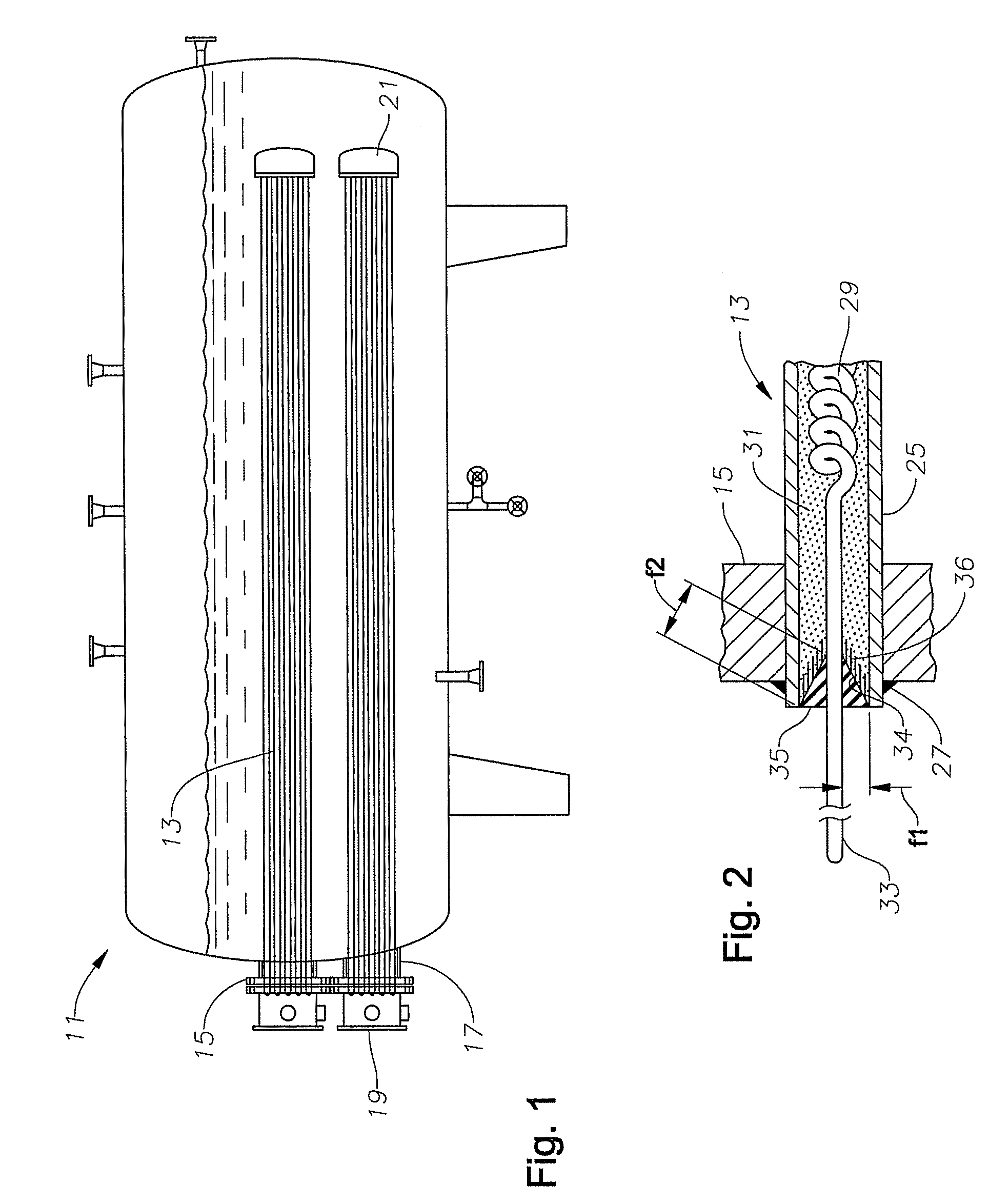
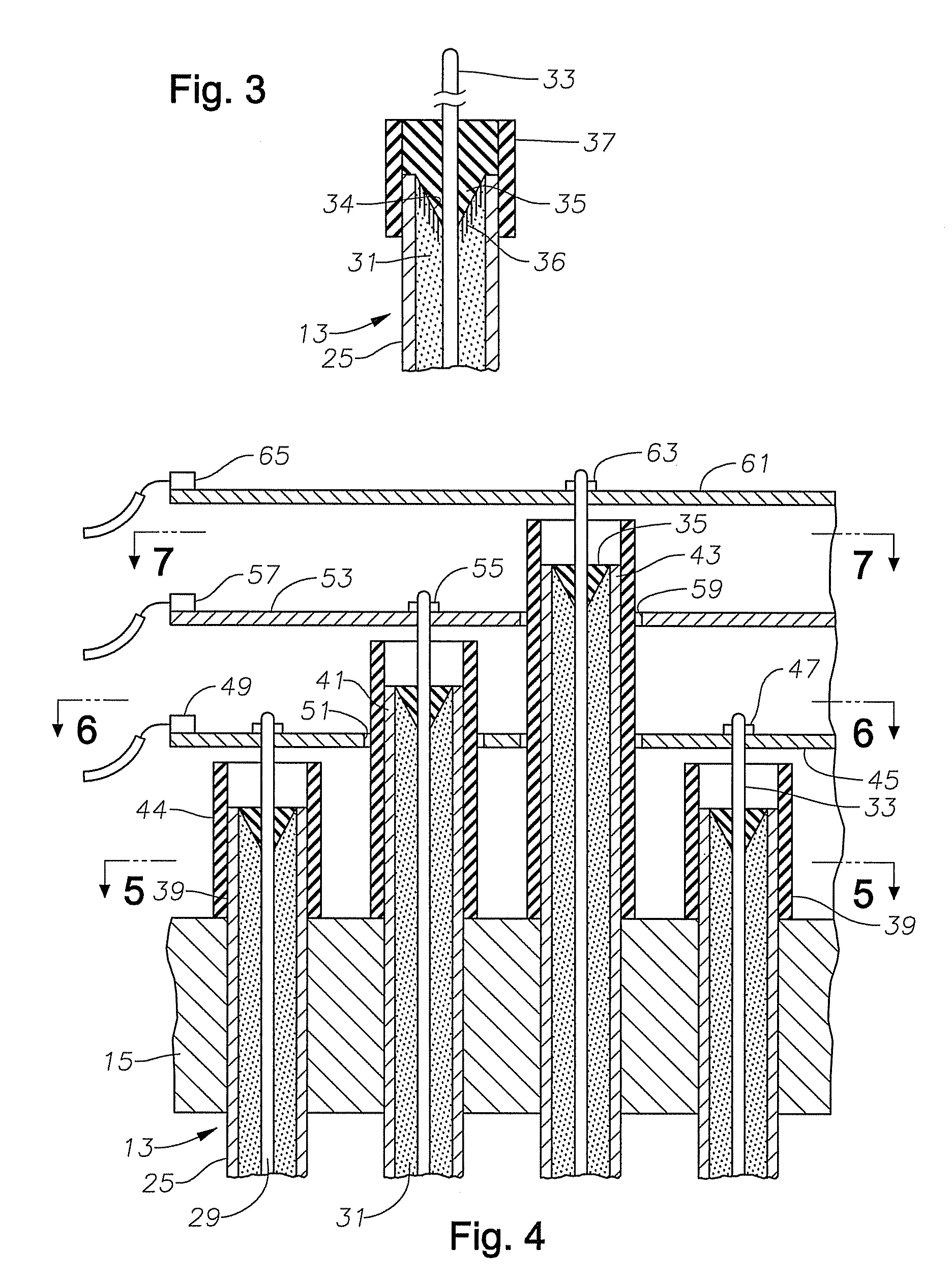
[0018]Referring to FIG. 1, a plurality of heater elements 13 extend into a tank 11 used for heat exchange purposes, typically in chemical and petroleum processing industries. Heater elements 13 preferably operate with three-phase AC power in the range from about 2,400 to 4,160 volts. Although considered a medium voltage for electrical power transmission in general, this voltage is higher than the voltages used typically with prior art process heat exchanger heater elements, typically about 600 to 640 volts. Heater elements 13 are shown in two separate bundles, but more or fewer bundles of heater elements 13 could be utilized. Heater elements 13 are tubular members that are immersed within water or other liquid for heating the liquid.

[0019]An exterior portion of each heater element 13 extends out of the front wall of tank 11 and through a header plate 15. In this embodiment, two separate header plates 15 are shown, one for each bundle of heater elements 13. Each header plate 15 has a...


PUM

PropertyMeasurementUnit
voltagesaaaaaaaaaa
viscosityaaaaaaaaaa
pressureaaaaaaaaaa

Abstract

An electrical heater bundle has heater elements, each including a metal tube, an electrical resistance coil within the tube, a conductor pin connected to the coil and protruding from an end of the tube, and an electrical insulation powder surrounding the coil within the tube. A conical cavity is located in the insulation powder at the end of the tube, the cavity extending from an inner diameter of the tube to the conductor pin. The cavity is filled with an epoxy that is cured in place. The insulation powder may have an infiltrated layer at the cavity that is an uncured liquid silicone. The heater elements are mounted to a header plate, and the elements associated with the three different phases of electrical power may protrude past the header plate at different distances.

Description

CROSS-REFERENCE TO RELATED APPLICATIONS[0001]This application claims priority to provisional application 60 / 796,400, filed May 1, 2006 and is a continuation-in-part from application Ser. No. 11 / 357,703, filed Feb. 17, 2006, which claimed priority to provisional application 60 / 653,763, filed Feb. 17, 2005.FIELD OF THE INVENTION[0002]This invention relates in general to heater elements for process heat exchangers, and in particular to heater elements that are constructed for voltages higher than normally utilized for process heat exchangers.BACKGROUND OF THE INVENTION[0003]One type of process heat exchanger used in various industries comprises a tank having an inlet and an outlet for the liquid to flow through. One or more heater element bundles are mounted in the tank. Each heater element bundle has a number of electrical resistance heater elements. Each heater element includes a metal tube, an electrical resistance coil within the tube and embedded in an insulation powder, and a con...

Claims


Application Information

Patent Timeline
Patent Type & Authority Patents(United States)
IPC IPC(8): H05B3/44
CPCF24H9/1818H05B3/44H05B3/82F24H1/202
Inventor MCCLANAHAN, JACK L.TIRAS, CRAIG S.FANNIN, JACKIE G.
Owner GAUMER
Why Eureka
Try Eureka