Method of operating a micromechanical device that contains anti-stiction gas-phase lubricant

a technology of anti-stiction gas and micro-mechanical devices, applied in nanotechnology, instruments, nanotechnology, etc., can solve problems such as device failure or malfunction, device “stiction” force created, stiction-type failure, etc., and achieve the effect of reliably preventing stiction-related device failures and higher rates

Inactive Publication Date: 2008-05-13
MIRADIA INC
View PDF43 Cites 19 Cited by
  • Summary
  • Abstract
  • Description
  • Claims
  • Application Information

AI Technical Summary

Benefits of technology

[0015]Embodiments of the invention may further provide a method of operating a micromechanical device comprising providing a micromechanical device that comprises a first contact surface, a moveable component having a second contact surface, wherein the second contact surface interacts with the first contact surface during device operation, and a liquid or solid lubricant material disposed on at least one of the first contact surface and the second contact surface, causing the second contact surface of the moveable component to interact repeatedly with the first contact surface, and disposing a gas-phase lubricant between the first contact surface and the second contact surface, wherein the gas-phase lubricant is adapted to increase the usable lifetime of the liquid or solid lubricant.
[0016]Embodiments of the invention may further provide a method of operating a micromechanical device comprising providing a micromechanical device that comprises a first contact surface, an electrode coupled to a base, and a mirror coupled to the base and having a conductive region, a reflective mirror surface and a second contact surface, wherein the second contact surface interacts with the first contact surface during device operation, and a power supply that is in electrical communication with the conductive region and the electrode, exposing the reflective mirror surface to optical radiation delivered from a light source, biasing the electrode relative to the conductive region to a potential that causes the mirror to move to a desired position and that causes the first contact surface to interact with the second contact surface, and disposing a gas-phase lubricant between the first contact surface and the second contact surface, wherein the gas-phase lubricant is adapted to reduce stiction between the first contact surface and the second contact surface.
[0017]One advantage of the disclosed micromechanical device is that a gas-phase lubricant diffuses at a substantially higher rate than conventional solid or liquid lubricants. A higher diffusion rate enables a gas-phase lubricant to be self-replenishing, meaning that the gas-phase lubricant can quickly move back into a contact region after being physically displaced from the region by the contacting surfaces of the electro-mechanical device during operation. Consequently, the gas-phase lubricant more reliably prevents stiction-related device failures relative to conventional solid or liquid lubricants.

Problems solved by technology

In particular, “stiction” forces created between moving parts that come into contact with one another, either intentionally or accidentally, during operation are a common problem with micromechanical devices.
Stiction-type failures occur when the interfacial attraction forces created between moving parts that come into contact with one another exceed restoring forces.
As a result, the surfaces of these parts either permanently or temporarily adhere to each other, causing device failure or malfunction.
The stiction issue is especially problematic in devices such as the RF switch, optical modulator, microgears, and other actuators.
Various analyses have shown that, without adding some form of lubrication to these types of devices to reduce stiction between component surfaces, product lifetimes may range from only a few contacts to a few thousand contacts, which is generally well below a commercially viable lifetime.
Consequently, one of the biggest challenges facing the MEMS and NEMS industries is the long-term reliability of contacting microstructures in the face of stiction.
Generally, these types of coatings have a very limited usable lifetime, since they are easily damaged or displaced due to impact or wear created by the interaction of the various moving components.
Without some way to reliably restore or repair the damaged coatings, stiction inevitably returns, and device failure results.
However, these lubricants typically diffuse away from or are physically displaced during normal device operation and oftentimes diffuse too slowly to reliably cover the exposed regions to reliably prevent stiction failures.
Another common problem is that liquid lubricants tend to break down during device operation to the point where they no longer provide proper lubrication.
This requirement introduces a host of problems related to providing reliable supplies of such lubricants.
However, adding the reversibly absorbing getter, or reservoirs, to retain the liquid lubricants increases package size and packaging complexity and adds steps to the fabrication process, thus increasing piece-part cost as well as the overall manufacturing cost of MEMS or NEMS devices.
Forming a device that uses these techniques will generally require a number of labor intensive and costly processing steps, such as mixing the getter material, applying the getter material to the device containing package, curing the getter material, conditioning or activating the getter material, and then sealing the MEMS device and the getter within the sealed package.
One such process is described in column 3, line 28 of U.S. Pat. No. 6,921,680, where it notes that “it is critical that the nebulizer system be maintained in a homogenous cloud of the lubricant around the device specimen.” These types of systems require additional steps to keep the concentration of the liquid droplets within the lubricant “fog” homogeneous which can be complex and costly.

Method used


Image

  • Method of operating a micromechanical device that contains anti-stiction gas-phase lubricant
  • Method of operating a micromechanical device that contains anti-stiction gas-phase lubricant
  • Method of operating a micromechanical device that contains anti-stiction gas-phase lubricant

Examples


Embodiment Construction

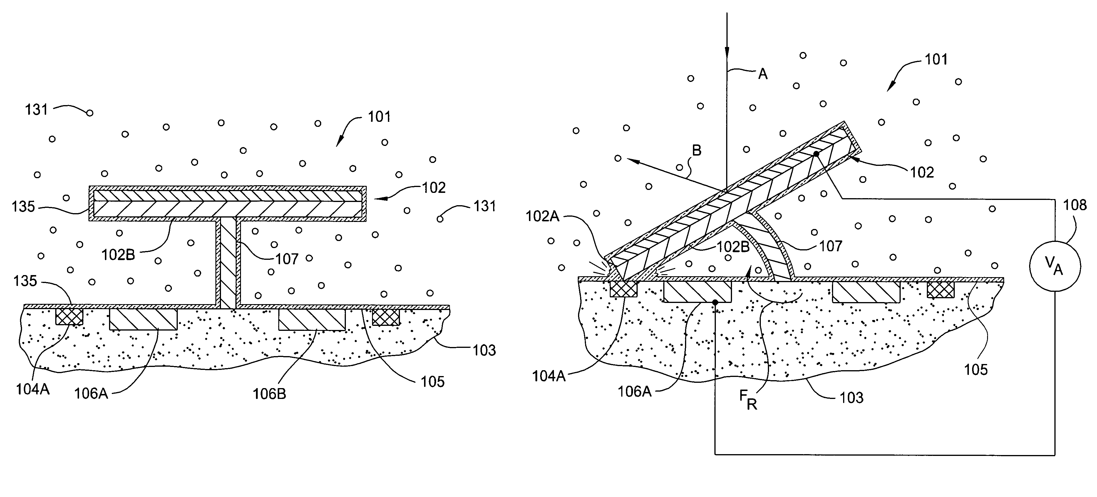
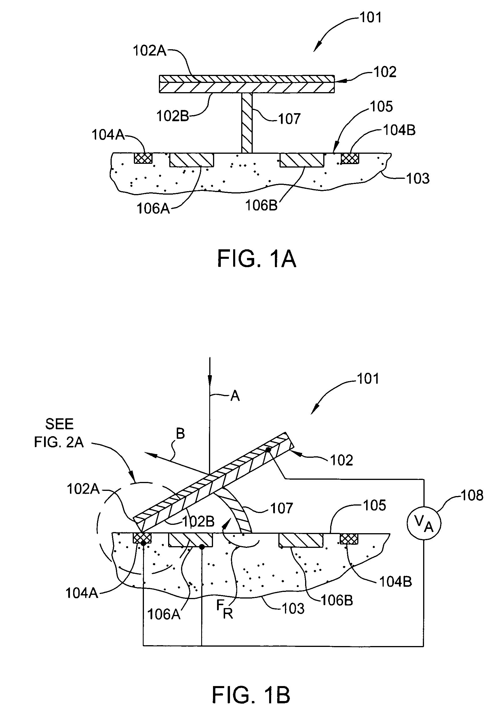
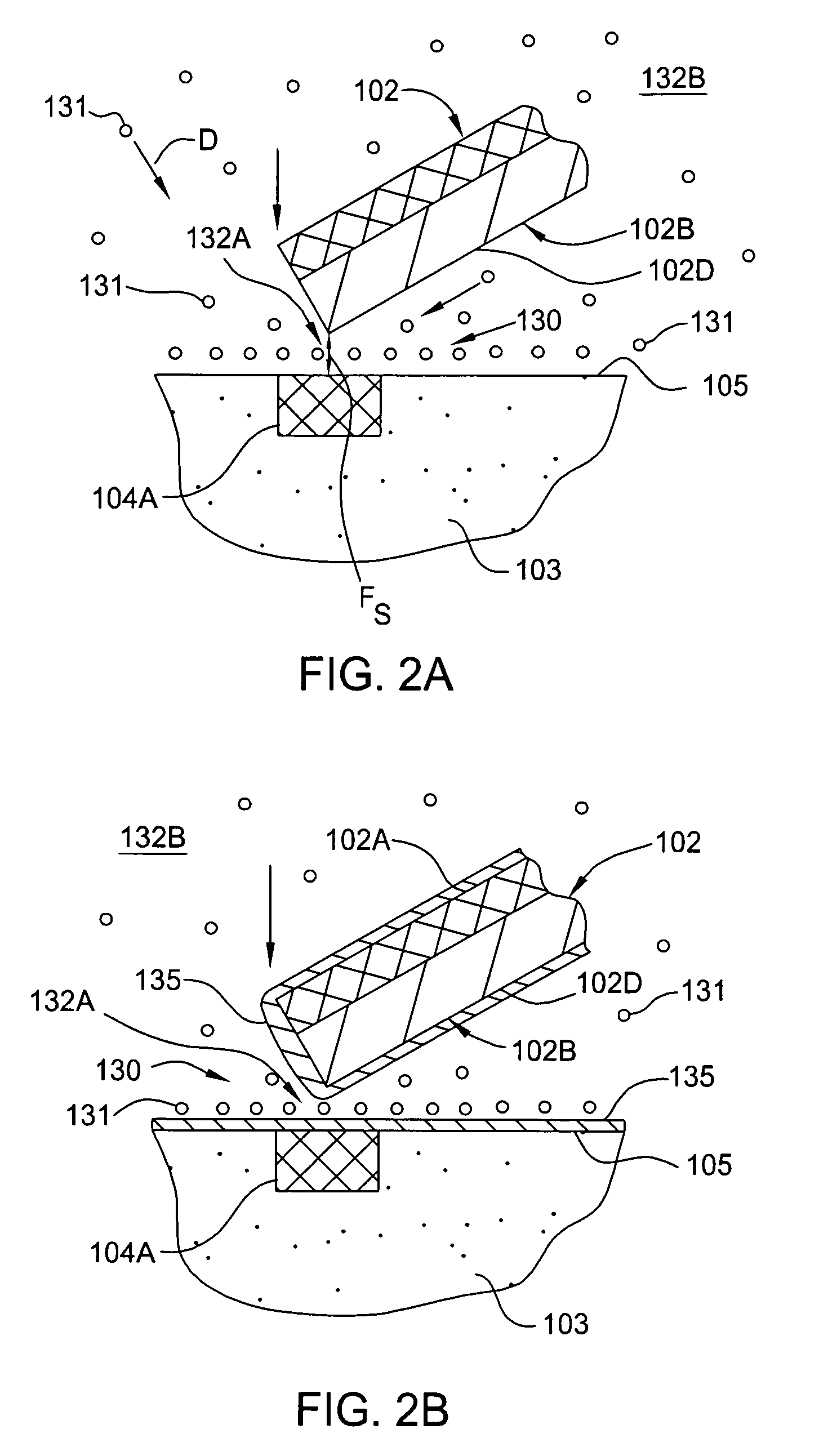
[0049]Embodiments of the present invention generally relate to a device that has an improved usable lifetime due to the addition of a gas-phase lubricant that reduces the likelihood of stiction occurring between the various moving parts in an electromechanical device. In one example, aspects of this invention may be especially useful for fabricating and using micromechanical devices, such as MEMS devices, NEMS devices, or other similar thermal or fluidic devices. In general, a gas-phase lubricant is disposed around components of such devices that interact with one another during operation to reduce the chances of stiction-related failures. One of skill in the art will recognize that the term lubricant, as used herein, is intended to describe a material adapted to provide lubrication, anti-stiction, and / or anti-wear properties. As described in further detail herein, the term gas-phase lubricant as used herein is generally intended to describe a lubricant that is in a gaseous state at...


PUM

PropertyMeasurementUnit
temperaturesaaaaaaaaaa

Abstract

One embodiment of an micromechanical device includes a first contact surface, a moveable component having a second contact surface, where the second contact surface interacts with the first contact surface during device operation, and a gas-phase lubricant disposed between the first contact surface and the second contact surface, where the gas-phase lubricant is adapted to reduce stiction-related forces between the first contact surface and the second contact surface. One advantage of the disclosed device is that a gas-phase lubricant has a high diffusion rate and, therefore, is self-replenishing, meaning that it can quickly move back into a contact region after being physically displaced from the region by the contacting surfaces of the device during operation. Consequently, the gas-phase lubricant is more reliable than conventional solid or liquid lubricants in preventing stiction-related device failures.

Description

CROSS-REFERENCE TO RELATED APPLICATIONS[0001]This application is a continuation of U.S. patent application Ser. No. 11 / 315,920, filed Dec. 22, 2005, which claims the benefit of U.S. provisional patent application Ser. No. 60 / 738,730, filed Nov. 23, 2005. Both of the applications are herein incorporated by reference.BACKGROUND OF THE INVENTION[0002]1. Field of the Invention[0003]Embodiments of the present invention relate generally to micro-electro-mechanical and nano-electro-mechanical systems and more specifically to an anti-stiction gas-phase lubricant for such systems.[0004]2. Description of the Related Art[0005]As is well-known, atomic level and microscopic level forces between device components become far more critical as devices become smaller. Micromechanical devices, such as Micro-electro-mechanical systems (MEMS) and nano-electro-mechanical systems (NEMS) is area where problems related to these types of forces are quite prevalent. In particular, “stiction” forces created be...

Claims


Application Information

Patent Timeline
Patent Type & Authority Patents(United States)
IPC IPC(8): G02B26/00G02F1/29
CPCB81B3/0005B81C1/0096G02B27/0006G02B21/32B81B2201/042B82Y30/00B81C2201/112G02B1/14
Inventor CHEN, DONGMINXIONG, FULIN
Owner MIRADIA INC
Why Eureka
Try Eureka