Multiplex communication system and method

a communication system and multi-mode technology, applied in the field of multiplex communication system and multi-mode system, can solve the problems of enormous damage, enormous amount of notification loss, and incredibly long time from the detection of faults to the completion of switching

Inactive Publication Date: 2008-05-13
NEC CORP
View PDF65 Cites 19 Cited by
  • Summary
  • Abstract
  • Description
  • Claims
  • Application Information

AI Technical Summary

Benefits of technology

[0014]A first object of the present invention is to provide a line switching system and the method, which can achieve switching of lines at a high-speed even in a system in which communication is achieved using a protocol without a switching function of lines without adding expensive hardware.
[0015]A second object of the present invention is to provide a line switching system and the method, which can achieve switching of lines at a high-speed even in a system in which communication is achieved using a protocol without a switching function of lines without changing the basic protocol in the network.

Problems solved by technology

Generation of a fault in such interface means interrupting a large amount of data so that the damage is enormous.
Thus, it takes an incredibly longer time from the detection of a fault to the completion of switching compared to a duplex switching by a protocol with a function of switching the lines such as SONET / SDH.
Therefore, an enormous amount of notification is o be lost during the time.
If there is a switching system as that in SONET / SDH to be applied at the point of transmitting the Ether frame, however, there is no such system in the standard of Ethernet®.
That is, in the case of achieving communication using a protocol without the function of switching the lines, it is time-consuming to perform duplex switching.
Further, if a new protocol is provided to achieve this, it becomes incompatible in regards to interface.
By defining a new protocol and terminating at a switching point, the interface becomes incompatible and the specification needs to be changed by each device.
Further, by terminating the protocol, the device becomes complicated thereby increasing the price.
Further, the wavelength multiplex optical communication system disclosed in Japanese Patent Application No. 11-150511 utilizes the line-switching function of the protocol so that it is not applicable to the protocol with no line-switching function.
Furthermore, conventionally, there are also problems in regards to an optical transmission switching device, a multiplex system, and Ethernet system, respectively, used in a multiplex communication.

Method used


Image

  • Multiplex communication system and method
  • Multiplex communication system and method
  • Multiplex communication system and method

Examples


Embodiment Construction

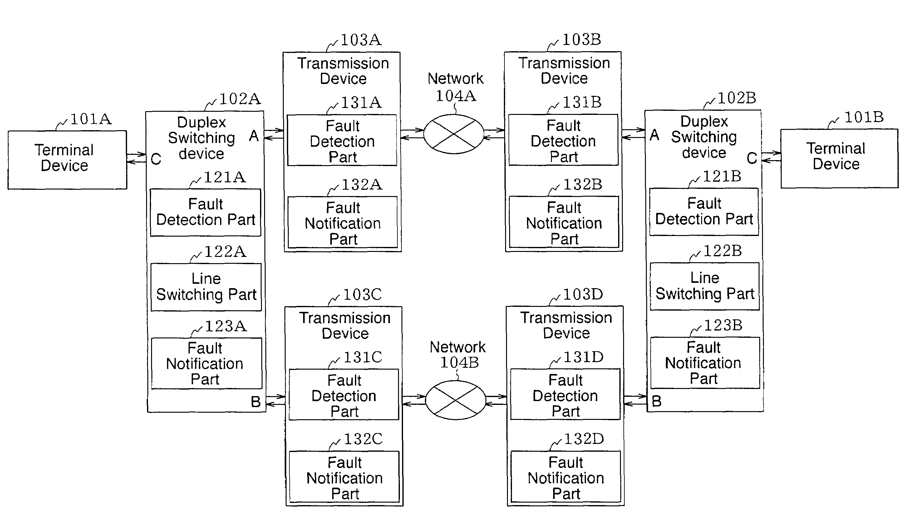
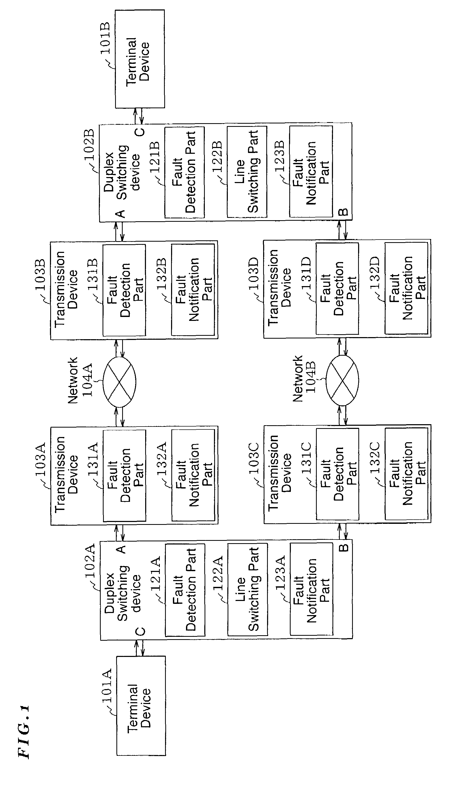
[0054]First, a line switching system in a multiples communication system according to the present invention will be described. The line switching system comprises a plurality of terminal devices and a plurality of line switching devices. In the system, at least one terminal device is connected to one line switching device and one line switching device is connected to another line switching device via a present line (line used for the present communication) and a standby line (standby system line), and one terminal device is connected to another terminal device prescribed beforehand to be capable of communication via a line switching device and a present line so that communication is achieved using a protocol without a line switching function. The standby line is a line replaceable with the present line. The line switching device of the system comprises: a fault detection unit for detecting generation of a fault through checking whether or not a recognizable signal is detected from a...


PUM


Abstract

Disclosed are the multiplex communication system and the method therefore. A fault detection part of a duplex switching device detects it as generation of fault when recognizable signals are not detected from a connected line within a prescribed time. When the fault detection part detects the generation of fault in the present system line, the line switching part switches the lines from the present line to the standby line to perform communication between a terminal device and another terminal device therethrough. Also, the fault detection part notifies the generation of fault to the other duplex switching device after a prescribed switching protection time has passed from the time of the fault detected by the fault detection part, so the selection of the lines becomes consistent.

Description

BACKGROUND OF THE INVENTION[0001]1. Field of the Invention[0002]The present invention relates to a line switching system, an optical transmission switching device, a multiplex system and an Ethernet redundant method and the system, which are best applicable to a multiplex communication, specifically, to communication using Ethernet®.[0003]2. Description of the Related Art[0004]When achieving the multiplex communication, a line switching system is employed in which a plurality of lines are provided within the communication system and switching of the line (communication path) to be used is performed when, for example, a communication fault is generated in some part of the line.[0005]As an example of a conventional data transmission system, there is a system comprising, in order to improve the reliability of the transmission, a present system line which is regularly used for communication and the standby system line, in which the line is switched to be used for the communication.[0006...

Claims


Application Information

Patent Timeline
Patent Type & Authority Patents(United States)
IPC IPC(8): G01R31/08H04L1/22H04L12/56
CPCH04J14/0287H04L1/22H04J14/0283H04L2012/5627
Inventor ARIKAWA, TOSHIAKIIKEMATSU, RYUUICHIHARADA, SHIGEKAZUISHIKAWA, HAJIMESUGITA, TAKAHIDESHINODA, HIDETOSHI
Owner NEC CORP
Why Eureka
Try Eureka