Method for bonding a body side wafer of a stoma system and a further component of said stoma system with each other

a stoma system and body side technology, applied in the field of stoma system and further component of stoma system bonding, can solve the problems of skin irritation, less suitable for stomas positioned in difficult positions, and less flexible and flat body side adhesive wafers

Active Publication Date: 2008-05-20
EUROTEC BEHEER
View PDF9 Cites 19 Cited by
  • Summary
  • Abstract
  • Description
  • Claims
  • Application Information

AI Technical Summary

Benefits of technology

[0013]For bonding a body side wafer of a stoma system and a further component of said stoma system to each other, the method according to the invention uses an ultrasonic welding apparatus comprising an anvil and a horn, wherein the horn comprises a first welding surface and the anvil comprises a second welding surface, wherein at least one of the first and second welding surfaces comprises a pattern of projections, preferably a plurality of adjacently placed conical projections such as pyramids, truncated pyramids, prismoids, cones, truncated cones or cylinders, wherein the method comprises the steps of clamping areas to be welded of the body side wafer and the further component between the first and second welding surface, and ultrasonically vibrate said horn with respect to said anvil. Said method results in a stoma system comprising a body side wafer and a further component, wherein the body side wafer and further component comprise respectively a first and a second welding area which are bonded to each other by ultrasonic welding, wherein at least one of said first and second welding areas comprises a pattern of depressions, preferably a plurality of adjacently placed conical depressions, preferably in a goffered, honeycomb or diamond pattern. In this way a strong and reliable bond can be obtained over the full welding area between the body side wafer and the further component so that they cannot be easily be torn apart.
[0017]In an embodiment the further component comprises a flange comprising a coupling member for coupling a stoma pouch with said flange. Preferably said flange is essentially circularly shaped with an upstanding or projecting rib as a coupling member, and said flange surrounds said aperture. Preferably the body side wafer comprises an aperture, and said flange is welded around said aperture. Preferably said horn comprises a circular first welding surface, enabling to weld said flange onto said body side flange in one go. Thus the weld of said flange completely surrounds the aperture and provides a sealing between said flange and said body side wafer, preventing any leakage between them.

Problems solved by technology

However, the major disadvantage of a one-piece system is that the adhesive has to be removed from the skin with every pouch change, which may cause skin irritations.
A major disadvantage of a two-piece stoma system is that the body side adhesive wafer is far less flexible and flat compared with a one-piece system because of the rigidity and the higher profile of the built-in coupling member, which makes it less suitable for stomas positioned in difficult areas such as folds and irregularities of the skin.
However this is not possible with the two-piece stoma system of Steer et al., since the relatively thick welding area of the flange hinders the transmission of heat to the thin film on the body side wafer.
The major disadvantage of this method is that it is a laborious intensive and expensive process.
The major disadvantage of this method is that manual bonding of the flange is very laborious intensive and in the case of a more automated production method the bonding process, owing to the need for accurate dosage, is very complicated and requires high investments.

Method used


Image

  • Method for bonding a body side wafer of a stoma system and a further component of said stoma system with each other
  • Method for bonding a body side wafer of a stoma system and a further component of said stoma system with each other
  • Method for bonding a body side wafer of a stoma system and a further component of said stoma system with each other

Examples


Embodiment Construction

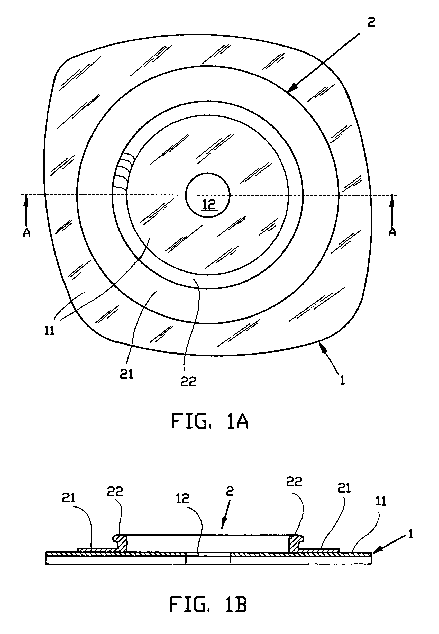
[0029]As an example, the method according to the invention is explained hereinbelow for the production of a body side wafer 1 with a round aperture 12 of a two-piece stoma system as shown in FIGS. 1A and 1B, with an integrated top layer of polyethylene 11. A disadvantage of this polyethylene film 11 is that it makes the body side wafer 1 rigid and less flexible. An advantage of this polyethylene film 11 is that is allows easy welding of the flange 2 by means of an ultrasonic welding technique, in particular where the composition of the polymeric flange 2 is at least partly identical or chemically equivalent to the polyethylene top layer 11 of the body side wafer 1.

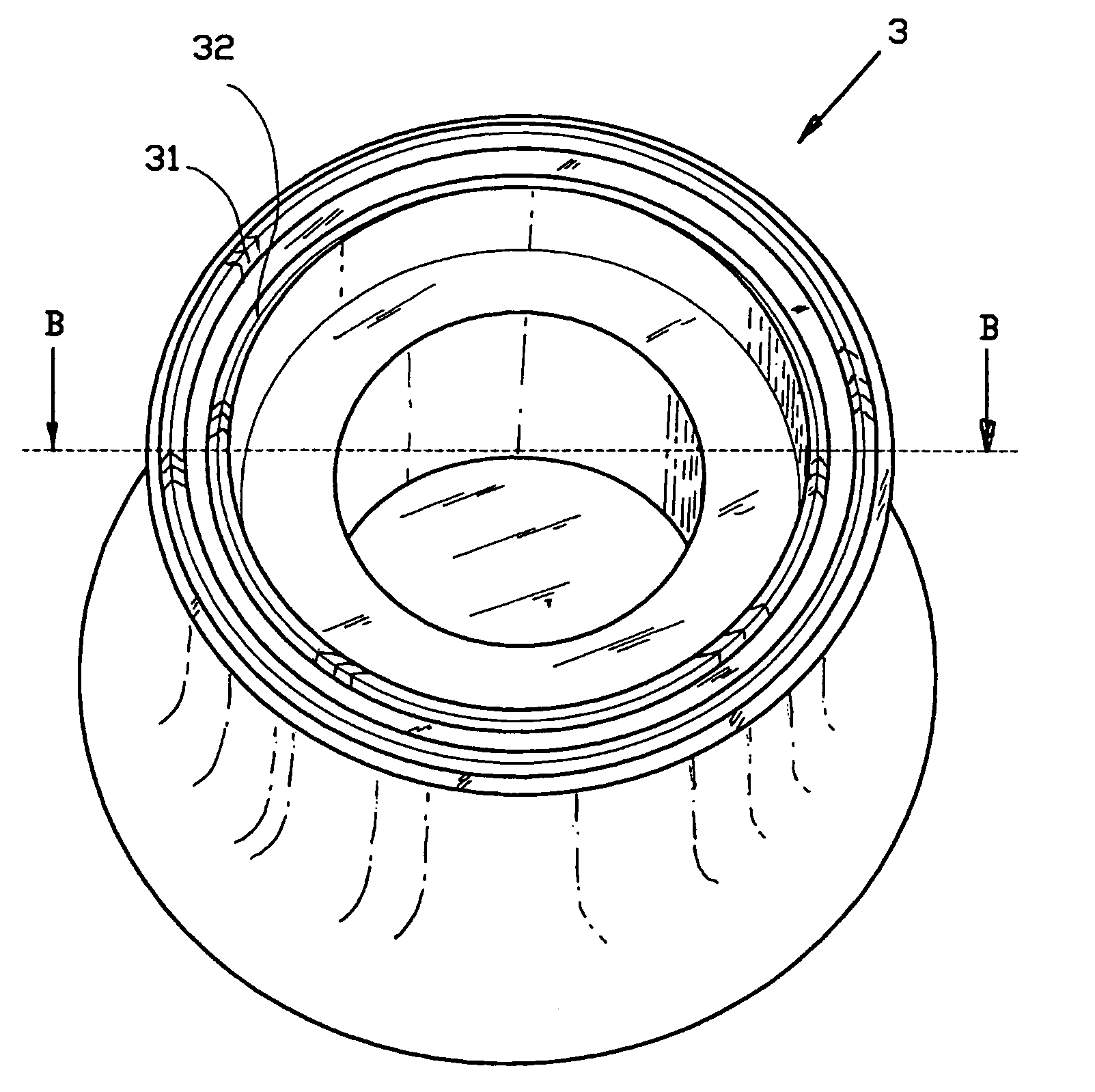
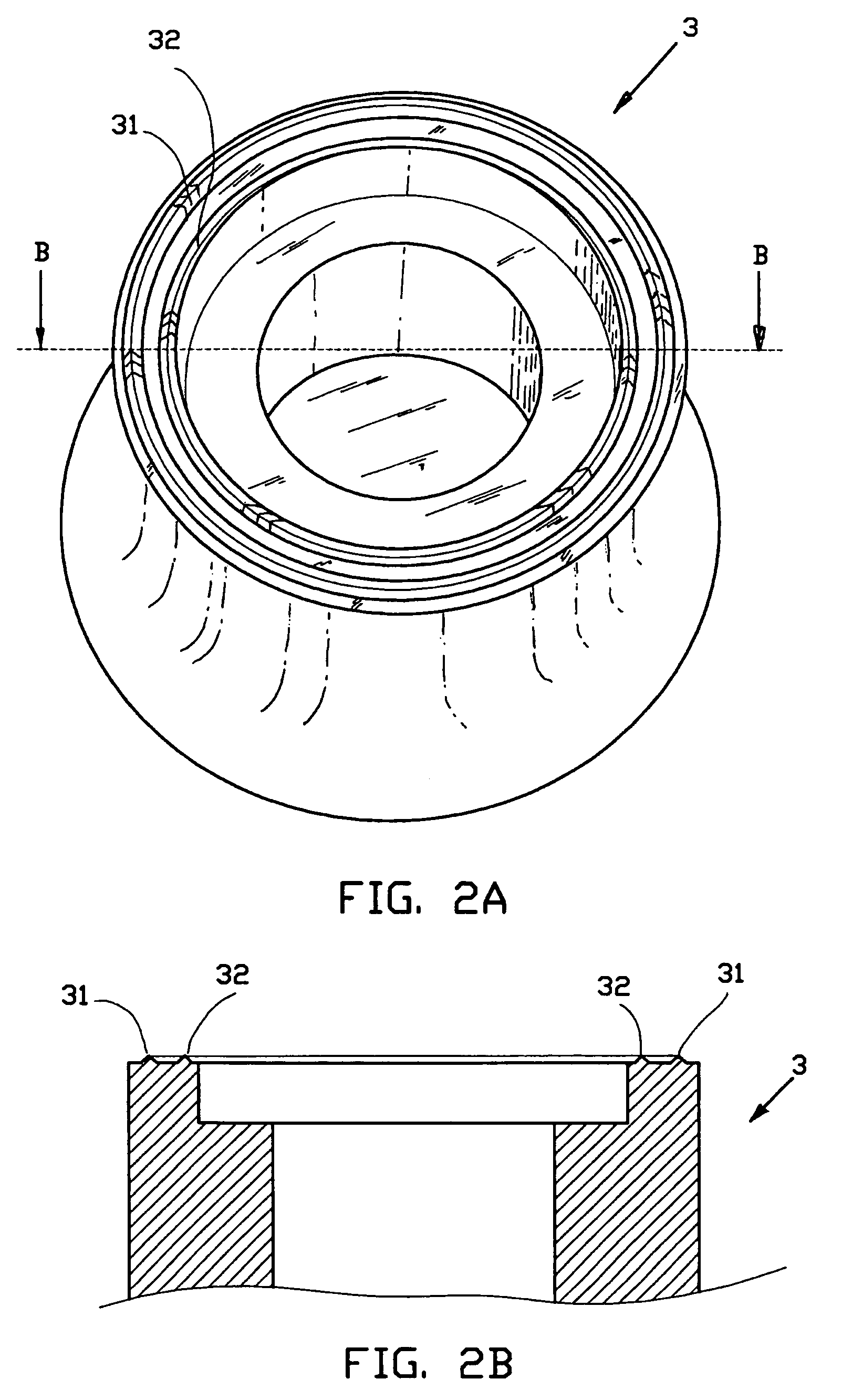
[0030]The flange 2 comprises a projecting rib 22 for the coupling of a stoma pouch (not shown) to the body side wafer 1. Furthermore the flange 2 is provided with an outwardly projecting sealing strip 21 for attaching the flange 2 onto the top layer 11 of the body side wafer 1, preferably by ultrasonic welding.

[0031]Ultras...


PUM

PropertyMeasurementUnit
areaaaaaaaaaaa
pressureaaaaaaaaaa
flexibleaaaaaaaaaa

Abstract

A body side wafer of a stoma system is bonded to a further component thereof using an ultrasonic welding apparatus including an anvil and a horn. The horn includes a first welding surface and the anvil includes a second welding surface. At least one of the two welding surfaces includes a pattern of projections, preferably a plurality of adjacently placed conical projections such as pyramids, truncated pyramids, prismoids, cones, truncated cones or cylinders. The steps include clamping the parts to be welded between the first and second welding surface, and ultrasonically vibrating the horn with respect to the anvil. The resulting welded structure includes a first and a second welding area, respectively, which are bonded to each other by ultrasonic welding. At least one of the two welding areas includes a pattern of depressions, preferably a plurality of adjacently placed conical depressions, preferably in a goffered, honeycomb or diamond pattern.

Description

FIELD OF THE INVENTION[0001]The invention relates to a method for bonding a body side wafer of a stoma system and a further component of said stoma system to each other, using an ultrasonic welding apparatus. The invention further relates to a stoma system comprising a body side wafer and a further component, wherein the body side wafer and further component comprise a first and a second welding area, respectively, which are bonded to each other by ultrasonic welding stoma systems, particularly in the United States, are also referred to as ostomy systems.BACKGROUND OF THE INVENTION[0002]A number of diseases involving the intestinal and urinary tracts can result in the construction of an artificial outlet on the abdominal area for stools and / or urine; this is referred to as a stoma.[0003]A diversion of the large intestine into the abdominal wall is referred to as a colostomy. The diversion of the small intestine is referred to as an ileostomy and when urine is disposed of through an ...

Claims


Application Information

Patent Timeline
Patent Type & Authority Patents(United States)
IPC IPC(8): B32B37/00A61F5/44A61F5/445B29C65/08
CPCA61F5/445B29C66/232B29C66/532B29C66/80B29C66/81427B29C66/81433B29C66/81425B29C66/474B29C66/81431B29C66/81435B29C66/727B29C65/08B29C66/9516B29L2031/7148B29C66/9512B29C66/71B29C66/7392B29C66/112B29C66/131B29C66/24221B29C66/1122B29K2023/06B29K2023/083
Inventor VAN DER LEDEN, ARIE GIJSBERT
Owner EUROTEC BEHEER
Why Eureka
Try Eureka