Automatic transmission electronic control device

a technology of electronic control device and automatic transmission, which is applied in the direction of electrical apparatus construction details, mechanical apparatus, transportation and packaging, etc., can solve the problems of thermal overshoot and increase the temperature of electronic control device, and achieve low heat conductivity, easy fixation of heat dissipating member, and low heat conduction

Inactive Publication Date: 2008-05-20
AISIN AW CO LTD
View PDF12 Cites 27 Cited by
  • Summary
  • Abstract
  • Description
  • Claims
  • Application Information

AI Technical Summary

Benefits of technology

[0007]It is an object of the present invention to provide an automatic transmission electronic control device which is able to maintain the temperature of its electronic circuit within its specified service temperature range to the extent possible and therefore maintain reliability at low cost.
[0008]Another object of the present invention is to provide a simple structure by which the electronic control device is able to dissipate heat when the temperature of the electronic control device is higher than the ambient temperature, and to provide a heat insulating effect when the ambient temperature rapidly becomes higher than the temperature in the electronic control device due to a thermal overshoot.
[0009]In an automatic transmission electronic control device in accordance with a first aspect of the present invention, a substrate provided with an electronic circuit for controlling an automatic transmission is contained in a liquid-tight enclosure formed of a material having a low heat conductivity, wherein the enclosure has a structure that dissipates the heat produced by the electronic circuit. Therefore, during operation of the automatic transmission, if the temperature of the electronic circuit becomes higher than the ambient temperature of the area surrounding the electronic control device (temperature inside of the casing), heat produced by the electronic circuit is dissipated via the enclosure so as to minimize the rise in the temperature of the electronic circuit and to prevent it from exceeding its service temperature range. Immediately after operation of the automatic transmission is stopped, the operating fluid, at a temperature which has become higher than that during operation, flows in from mechanisms operated at a high-temperature, such as torque converter, oil pump, etc., and therefore rapidly raises the temperature of the electronic control device, resulting in a thermal overshoot. Any thermal overshoot is absorbed by the enclosure, having a low heat conductivity, to curb the rapid rise in the temperature of the electronic circuit which would otherwise occur and to prevent its temperature from exceeding the service temperature range. Therefore, reliability can be maintained at low cost with a simple structure by maintaining the temperature of the electronic circuit within the conventional service temperature range to the extent possible.

Problems solved by technology

Immediately after operation of the automatic transmission is stopped, the operating fluid, at a temperature which has become higher than that during operation, flows in from mechanisms operated at a high-temperature, such as torque converter, oil pump, etc., and therefore rapidly raises the temperature of the electronic control device, resulting in a thermal overshoot.

Method used


Image

  • Automatic transmission electronic control device
  • Automatic transmission electronic control device
  • Automatic transmission electronic control device

Examples


first embodiment

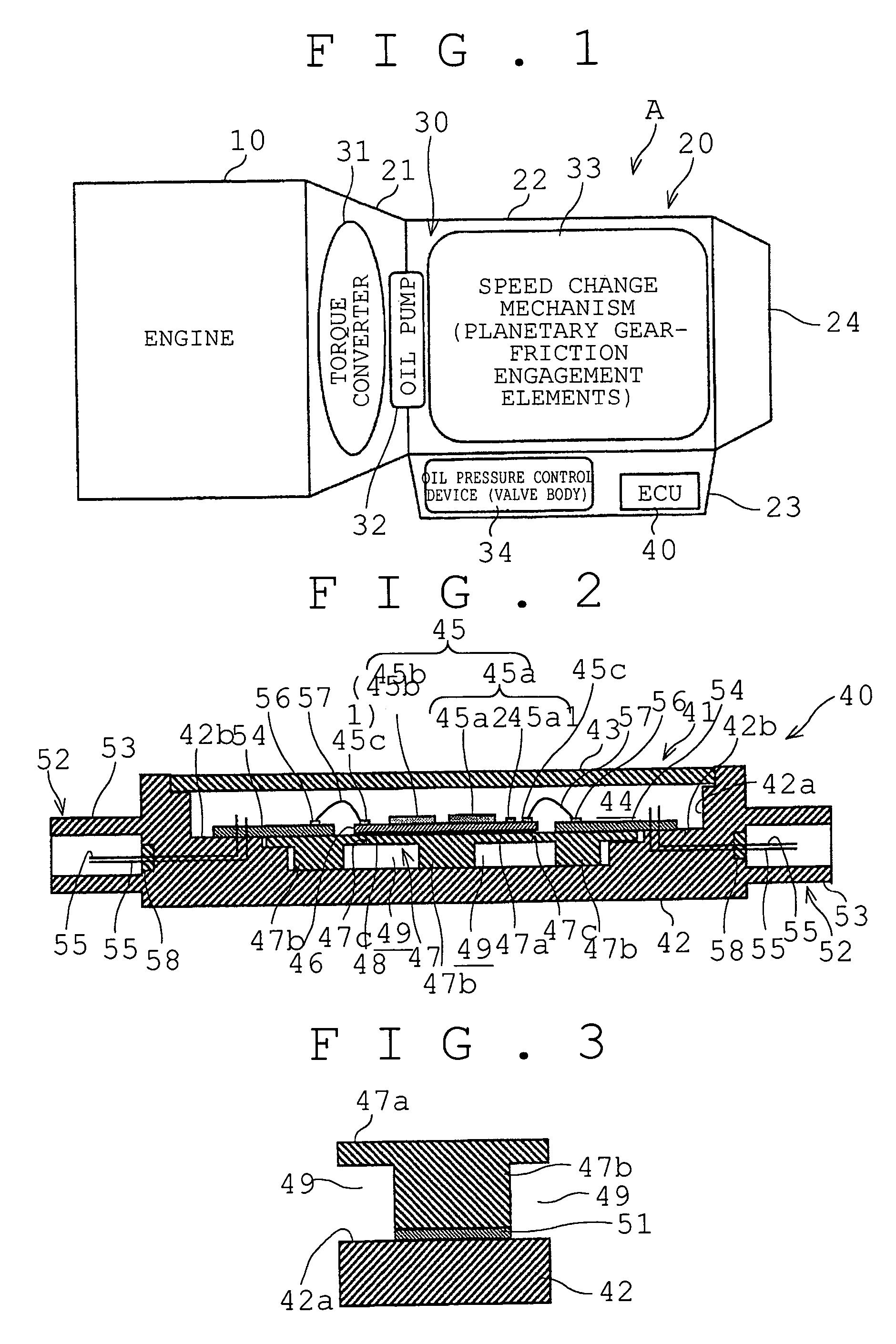
[0034]An automatic transmission A equipped with an automatic transmission electronic control device of a first embodiment of the present invention will be described hereinafter with reference to the drawings. FIG. 1 shows the automatic transmission A which changes the speed of the output of an engine 10 mounted in a vehicle, and transfers power to driving wheels. In this embodiment, the automatic transmission A is a FR (front engine, rear drive) vehicle automatic transmission, and is located at the rear of the engine 10. The present invention is also applicable to a FF (front engine, front drive) vehicle automatic transmission.

[0035]The automatic transmission A is provided with a casing 20 that houses an operating mechanism 30. Automatic Transmission Fluid (ATF or AT), is utilized by the operating mechanism 30.

[0036]The operating mechanism 30 includes a torque converter 31, an oil pump 32, a speed change mechanism 33, and an oil pressure control device (valve body) 34. The torque co...

second embodiment

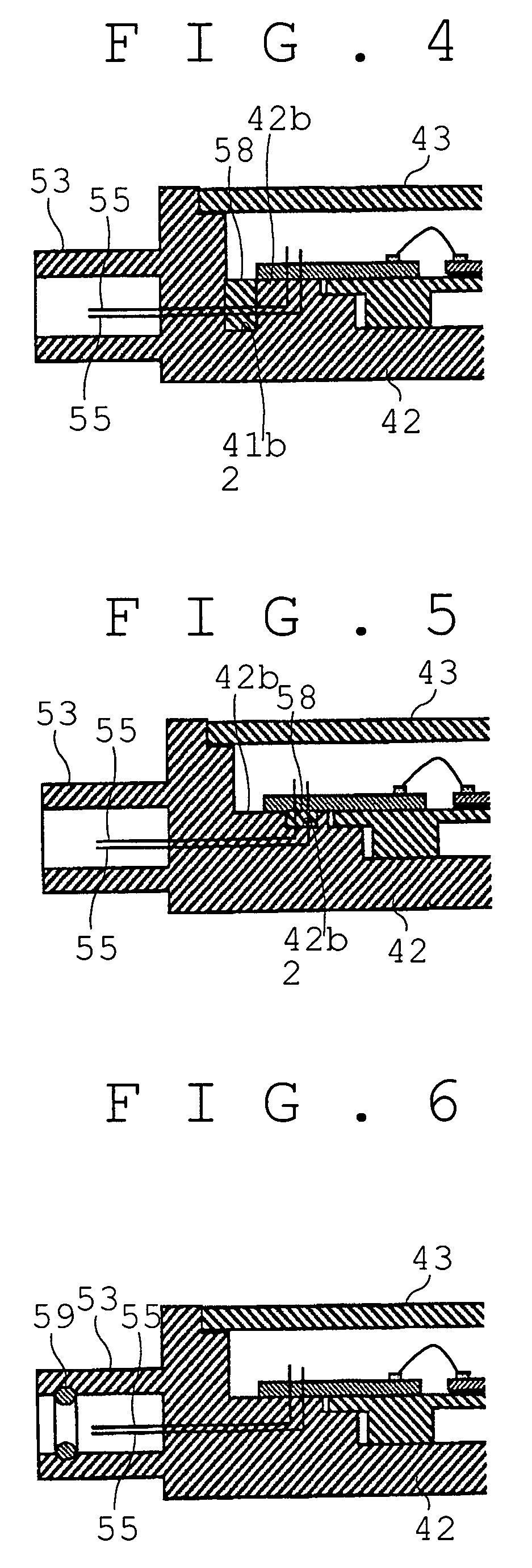
[0060]Next, an automatic transmission electronic control device in accordance with a second embodiment of the present invention will be described with reference to FIGS. 7 and 8. While in the first embodiment the substrate 46 and the relay substrate 54 are separate members, the second embodiment includes a substrate 146 in which the substrate 46 and the relay substrate 54 are integrated. Other features of the second embodiment that are substantially the same as those of the first embodiment are represented by the same reference numerals, and the description thereof will not be repeated and only those feature different from the first embodiment will be described.

[0061]The substrate 146 is formed of a glass epoxy. As in the substrate 46, an upper surface of the substrate 146 has an electronic circuit45 formed thereon. Pins 55 are soldered to the upper surface of the substrate 146 and the electronic circuit 45 and the pins 55 are electrically connected by a pattern disposed on the uppe...

third embodiment

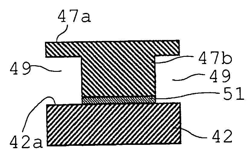
[0063]Next, an automatic transmission electronic control device in accordance with a third embodiment of the present invention will be described with reference to FIG. 9. While in the first embodiment, the heat sink 47 is in contact with the bottom surface of the recess 42a of the body 42, and is adhered thereto by the adhesive 51, the third embodiment adopts a structure in which a heat sink 247 is insert-molded in the bottom surface of the recess 42a. In this case, the heat sink 247 is provided with protrusions 247a for securing the heat sink 247 within the case body 42. Incidentally, portions of the third embodiment that are substantially the same as those of the first embodiment are represented by the same reference numerals, and only those features which are different will be described here. This embodiment reduces the cost and labor involved in attaching the heat sink 247 to the enclosure 41.


PUM


Abstract

An ECU has an enclosure which is contained in the casing of an automatic transmission, which is formed of a material having low heat conductivity, and which provides liquid-tight containment of a substrate. A heat sink is attached to the substrate so as to dissipate heat from an electronic circuit on the substrate. The heat sink is attached in contact with an inner wall surface of the enclosure, so that heat produced by the electronic circuit is dissipated via the heat sink and the enclosure.

Description

INCORPORATION BY REFERENCE[0001]The disclosure of Japanese Patent Application No. 2004-222559 filed on Jul. 29, 2004 including the specification, drawings and abstract is incorporated herein by reference in its entirety.BACKGROUND OF THE INVENTION[0002]1. Field of the Invention[0003]The present invention relates to an automatic transmission electronic control device which is attached within a casing of an automatic transmission.[0004]2. Description of the Related Art[0005]A conventionally known automatic transmission electronic control device of the aforementioned type has a substrate which is attached within a casing of an automatic transmission and which includes an electronic circuit for operating the automatic transmission (see Japanese Patent Application Laid-Open Publication No. 2002-12097 (pp. 3-6, and FIGS. 1-8)). The vehicular electronic control device described in this publication has an insulating sheet 24 and, mounted on its upper surface, a control unit 33 that controls...

Claims


Application Information

Patent Timeline
Patent Type & Authority Patents(United States)
IPC IPC(8): H05K7/20
CPCB60R16/0239F16H61/0006H05K7/20854H05K5/0082
Inventor MURAKAMI, NAOTAKAMASAKI, HIROYUKI
Owner AISIN AW CO LTD
Why Eureka
Try Eureka