Apparatus and method for expanding a stimulation lead body in situ

a technology of electrodes and lead bodies, applied in the field of implantable leads, can solve the problems of large passage through the vertebral bone, limited types of lead structures that may be incorporated into percutaneous leads, and the need for laminectomies, etc., and achieve the effect of convenient insertion

Inactive Publication Date: 2008-05-20
MEDTRONIC INC
View PDF84 Cites 36 Cited by
  • Summary
  • Abstract
  • Description
  • Claims
  • Application Information

AI Technical Summary

Benefits of technology

[0015]The invention combines the advantages of percutaneous leads with those of paddle leads. In a preferred embodiment, the invention provides a lead structure including a central core portion and at least one flexible, semi-flexible or semi-rigid transversely extending span which may be positioned in a compact position during insertion in which it is wound around or otherwise disposed in close proximity to the central core portion. Each span may also be deployed or shifted to a position in which it extends outward from the central core portion in a transverse direction. Each span has disposed on one surface a number of therapy delivery elements, in the form of electrodes or catheter ports, for delivering therapy in the respective form of electrical or drug therapy to the body. In the compact insertion position, the lead may be easily inserted within a catheter or Tuohy needle. Once the lead has been positioned at the appropriate place in the body, the span or spans may be deployed from the compact position to the extended position in which the therapy delivery elements are positioned in a fashion similar to a paddle lead. The flexibility of the spans also permits the lead to be retracted back to the compact position in the event that the lead must be removed from the body.
[0016]In a preferred embodiment, the invention provides a lead which includes a central core portion and at least one flexible paddle extending therefrom and which may be coiled around the core portion when the lead is to be compacted for insertion. As the lead is inserted through a catheter or Tuohy needle, the spans are kept in the compact position by lead rotation in a direction opposite their direction of winding around the central core. Also according to the invention, the spans are deployed by rotating the central core portion in the same direction in which the spans are coiled around the central core portion. Because of the flexibility of the spans, they are caused to move outward, away from the central core as the lead is uncoiled. In another embodiment of the invention, the spans can be formed of a resilient material in which resilient forces develop when the lead is configured in its compact position. The lead is maintained in its compacted form while inside of the insertion tool, i.e. Tuohy needle. The resilient forces cause the spans to extend outward once the lead exits the end of the insertion tool.
[0017]An outer concentric retainer tube may be provided in combination with the lead, the outer retainer tube acting to retain the lead in its compact position during insertion. The retainer tube may be provided with a pair of notches on its distal end to aid in the retraction of the lead after deployment. Specifically, the notches are disposed on the distal end of the retainer tube in such a manner that the spans will engage the notches when the central core portion is rotated and pulled toward a proximal end of the retainer tube. The notches retain the spans in position as the central core rotates, thus causing the spans to coil around the central core portion and assume a compact position.

Problems solved by technology

On the other hand the types of lead structure, including the electrodes or drug-delivery catheters, that may be incorporated into percutaneous leads is limited because the lead diameter or cross-section must be small enough to permit the lead to pass through the Tuohy needle.
One disadvantage recognized in known paddle leads is that their installation, repositioning and removal necessitates laminectomies, which are major back surgeries involving removal of part of the vertebral bone.
Thus, implantation, repositioning and removal require a rather large passage through the vertebral bone.
Another disadvantage with paddle leads is that optimal positioning is often difficult during implant.
Such placement is difficult since the doctor cannot see the spinal cord thru the dura during implant.
Moreover, lead shifting may occur subsequent to implant, thereby affecting the efficacy of the therapy delivered from the lead.
Yet another disadvantage recognized with paddle leads is that the lead position may change merely with patient movement.
While the prior art has attempted to provide deformable leads, which may provide improved insertion characteristics or enhanced stability once inside the body, they have not succeeded in providing a device which remedies the aforementioned problems.
In Mullett's device, only one electrode can be found at any particular longitudinal location, since only gentle curves of the lead were designed, and the curves are not adjustable after implant of the lead.
Similar problems apply to the device disclosed by O'Neill in U.S. Pat. No. 4,154,247.
While this could give two electrodes at the same longitudinal position, their medial to lateral locations are difficult to control, and their ability to spread apart depends on the relative stresses in the spans and tissue-like adhesions that may be present.
While the aforementioned prior art devices provide various configurations for compact insertion or lead stabilization after implant, they do not offer the advantages and improved efficacy recognized with respect to paddle lead configurations.

Method used


Image

  • Apparatus and method for expanding a stimulation lead body in situ
  • Apparatus and method for expanding a stimulation lead body in situ
  • Apparatus and method for expanding a stimulation lead body in situ

Examples


Embodiment Construction

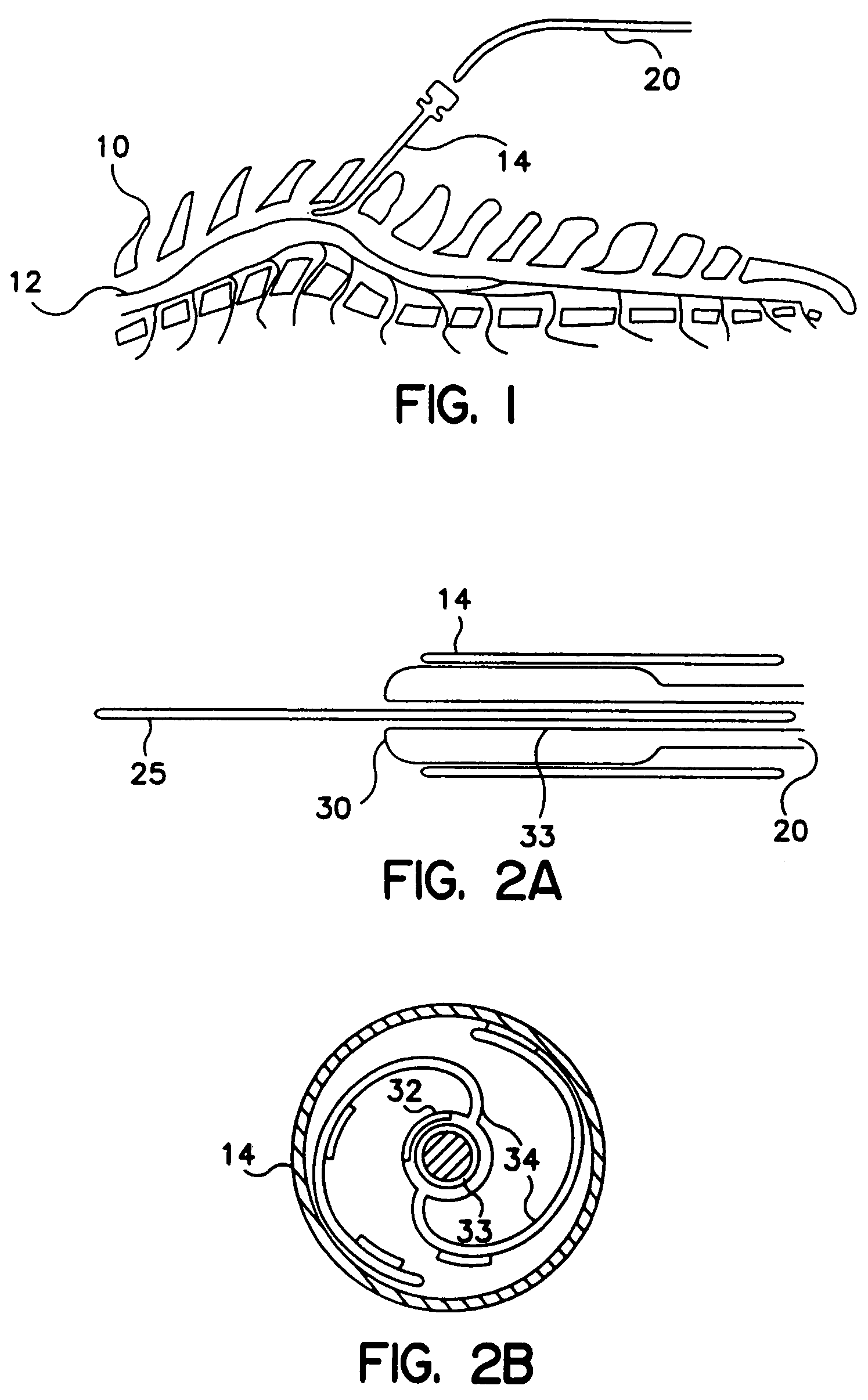
[0056]FIG. 1 illustrates a lead according to a preferred embodiment of the invention being utilized in an SCS implementation. In accordance with known techniques, a Tuohy needle 14 is positioned near the dura 12 of spine 10. Lead body 20 is inserted through the lumen of s Tuohy needle 14 and positioned near the dura 12. A proximal end (not shown) of lead body 20 is connected to a source device (not shown) which may be a pulse generator, in the case of electrical stimulation, or a drug pump in the case of drug therapy. Although the invention will be described herein with reference to SCS procedures and the embodiments described in relation to electrical therapy, it will be recognized that the invention finds utility in applications to other than SCS procedures, including other applications such as Peripheral Nervous System (PNS) Stimulation, Sacral Root Stimulation, Cortical Surface Stimulation or Intravecular Cerebral Stimulation. In addition, the invention finds applicability to SC...


PUM


Abstract

An implantable lead is provided with at least one extendable member to position therapy delivery elements, which may be electrodes or drug delivery ports, after the lead has been inserted into the body. The lead may formed as a resilient element which is contained in a retainer tube that may be removed to permit the lead to deploy. Alternatively, a non-resilient lead may be provided with a slotted retainer tube. A series of mechanical linkages for expanding and retracting the lead within the human body may be actuated with various mechanisms. A control system may be provided for closed-loop feedback control of the position of the extendable members. The invention also includes a method for expanding an implantable lead in situ.

Description

RELATED APPLICATION[0001]This is a continuation of 10 / 158,521, filed May 30, 2002, now U.S. Pat. No. 6,714,822 which is a divisional application of U.S. Ser. No. 09 / 862,104 filed May 21, 2001, now U.S. Pat. No. 6,442,435 which is a continuation of application Ser. No. 09 / 584,572 filed May 31, 2000, now U.S. Pat. No. 6,292,702, which is a divisional of U.S. Pat. No. 09 / 070,136 filed Apr. 30, 1998, now U.S. Pat. No. 6,161,047 for which priority is claimed.BACKGROUND OF THE INVENTION[0002]This invention relates to implantable leads for delivering therapy, in the form of electrical stimulation or drugs, to the human body. Specifically, this invention relates to implantable leads that may be expanded, retracted or adjusted after implantation in the human body. This invention also relates to mechanisms for accomplishing such expansion, retraction or adjustment of such leads in situ. Further, this invention relates to control systems for controlling such expansion, retraction or adjustment...

Claims


Application Information

Patent Timeline
Patent Type & Authority Patents(United States)
IPC IPC(8): A61N1/05A61M5/142A61M5/172
CPCA61M5/14276A61N1/05A61N1/0551A61N1/0558A61M5/1723A61M2209/045A61M2210/0693A61M2210/1003A61N1/056
Inventor KING, GARY W.RISE, MARK T.SCHENDEL, MICHAEL J.SCHALLHORN, RICHARD
Owner MEDTRONIC INC
Why Eureka
Try Eureka