Gas jet cooling device

a cooling device and gas jet technology, applied in the field of gas jet cooling devices, can solve the problems of increasing the construction cost the inability to secure the mechanical properties of each product, and the inability to control the intended cooling end temperature of each steel strip, so as to reduce the size of the cooling chamber, shorten the distance between the metal strips, and quickly and uniformly cool the metal strips.

Active Publication Date: 2008-06-03
KOBE STEEL LTD
View PDF6 Cites 6 Cited by
  • Summary
  • Abstract
  • Description
  • Claims
  • Application Information

AI Technical Summary

Benefits of technology

[0007]The present invention has been established in view of the above situation, and the object thereof is to provide: a gas jet cooling device for a steel strip in a continuous annealing furnace that improves the aforementioned problems of the prior art and is capable of cooling the steel strip rapidly and uniformly even when the distance between the steel strip and the front face of a windbox is short and the size of a cooling chamber is small; in other words, a gas jet cooling device for a steel strip in a continuous annealing furnace that secures the capability of the rapid and uniform cooling of the steel strip and, on top of that, is capable of shortening the distance between the steel strip and the front face of a windbox and thus reducing the size of a cooling chamber.
[0008]The present inventors have earnestly studied to attain the aforementioned object and have resultantly established the present invention. The present invention makes it possible to attain the aforementioned object.
[0017]A gas jet cooling device according to the present invention makes it possible to cool a metal strip rapidly and uniformly even when the distance between the metal strip and the front face of a windbox is short and the size of a cooling chamber is small. In other words, it makes it possible to secure the capability of the rapid and uniform cooling of a metal strip, on top of that, to shorten the distance between the metal strip and the front face of a windbox, and thus to reduce the size of a cooling chamber.

Problems solved by technology

As a result, when the steel strips the intended mechanical properties of which are different from each other are continuously processed and thus the cooling conditions are different between the preceding steel strip and the succeeding steel strip, the controllability of the intended cooling end temperature of each steel strip lowers and moreover the mechanical properties of each product can hardly be secured.
Further, another arising problem is that it causes the construction cost of a cooling chamber to increase.

Method used


Image

  • Gas jet cooling device
  • Gas jet cooling device
  • Gas jet cooling device

Examples


example a

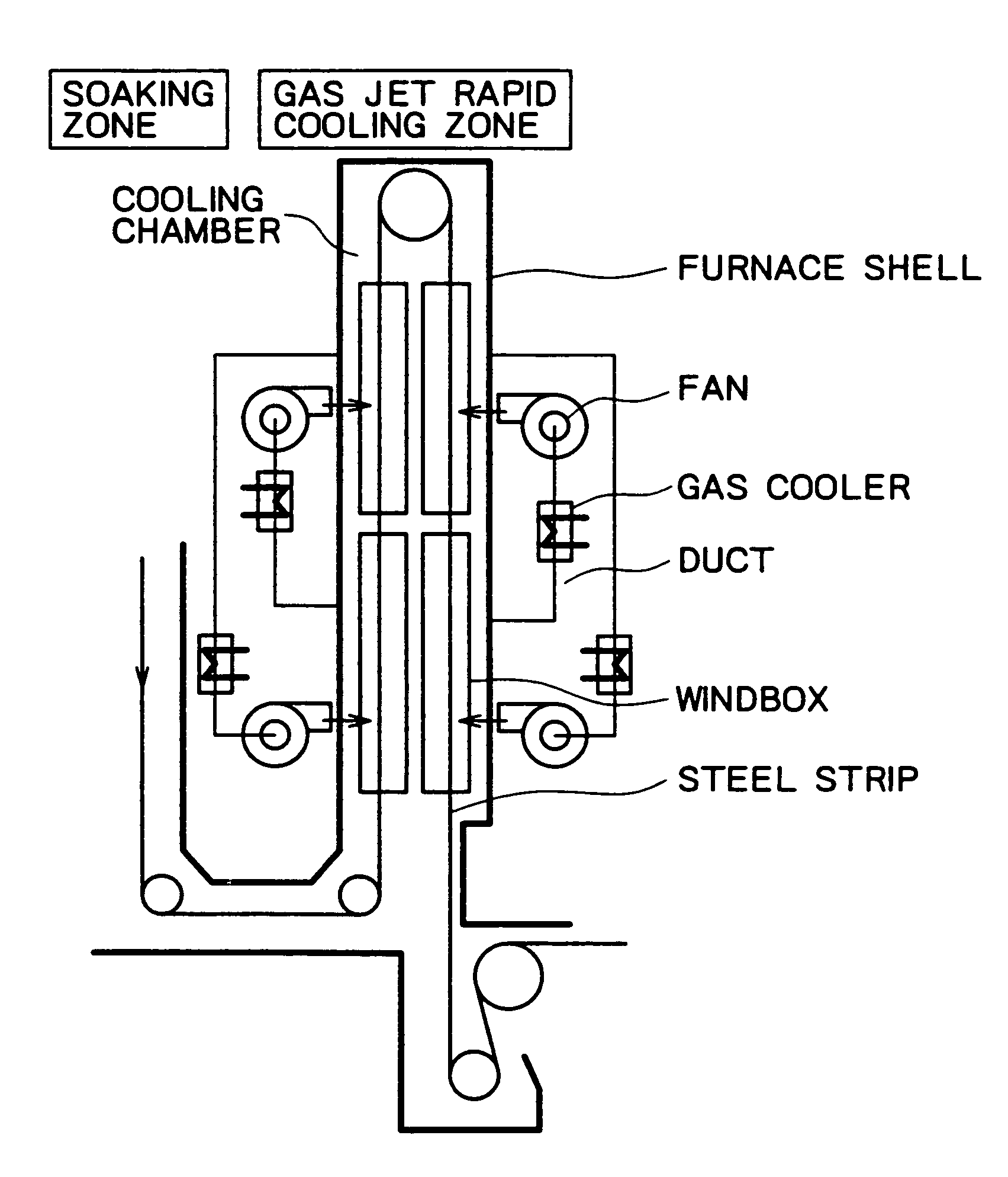
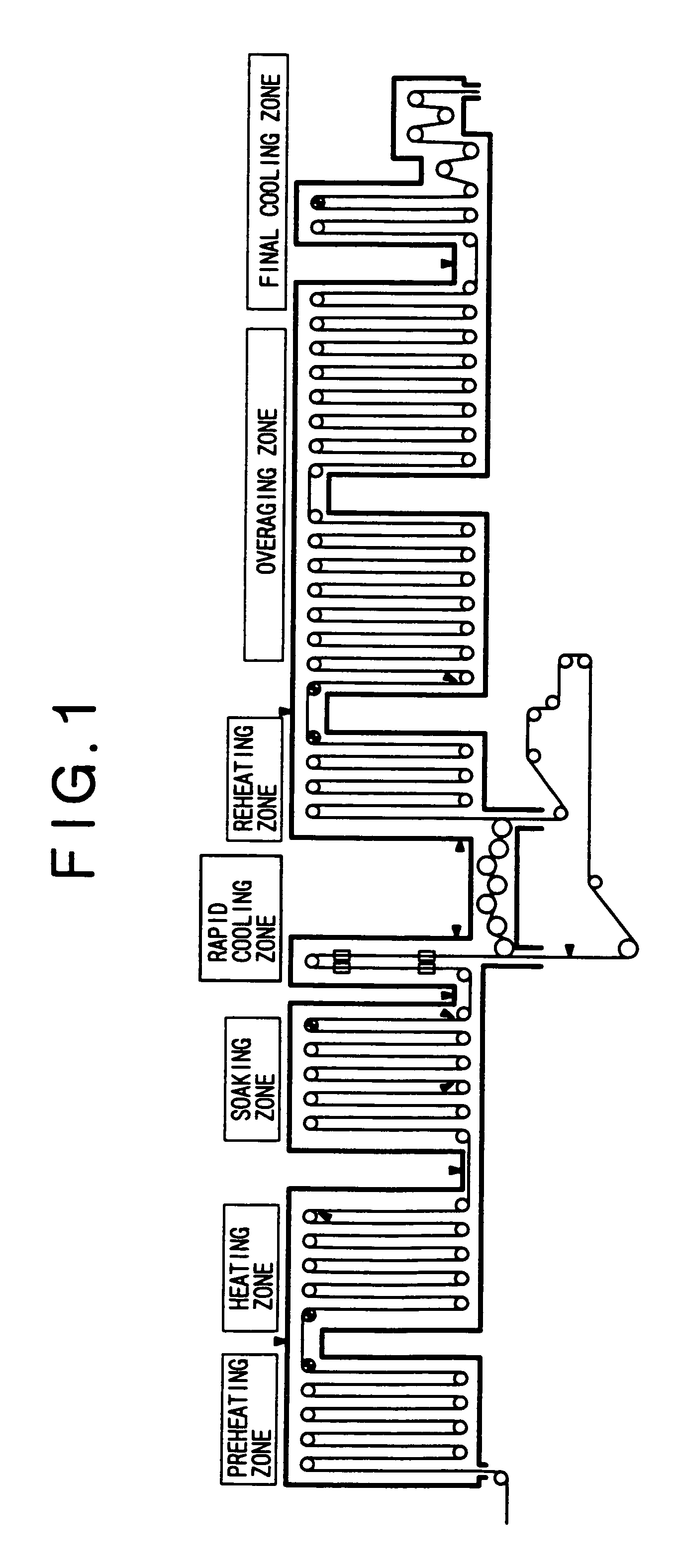
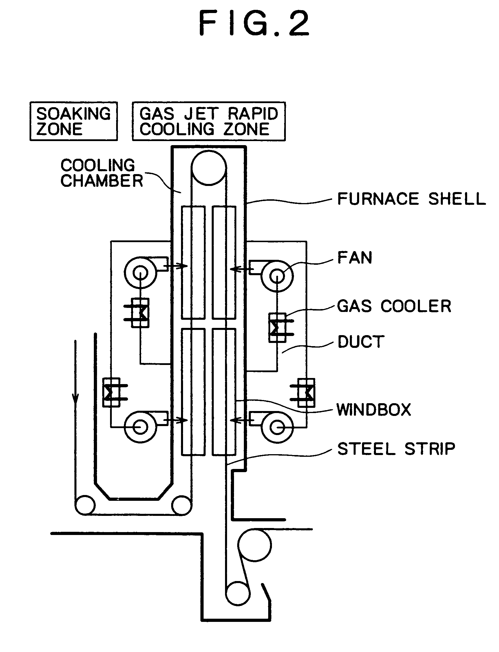
[0062]As a continuous annealing furnace, the one shown in FIG. 1 was used. A gas jet cooling device was installed in the rapid cooling zone of the continuous annealing furnace. As the gas jet cooling device, the same one as shown in FIG. 2 was used. As windboxes of the gas jet cooling device, the same ones as shown in FIG. 4 were used (however, the allocation of the nozzle hole group was varied). The nozzles on each of the windboxes did not protrude and were composed of a group of round holes disposed on the front face of each windbox, and the holes were allocated so as to form a staggered pattern. The intervals of the nozzles (the distance between a nozzle and an adjacent nozzle) were 50 mm.

[0063]Since the nozzles of each windbox did not protrude as explained above, the distance (h) between the tips of the nozzles on each windbox and a steel strip equaled the distance between the front face of each windbox and the steel strip. The distance h was set at 50 mm. The diameter (d) of th...

example b

[0075]As a continuous annealing furnace, the one shown in FIG. 1 was used. A gas jet cooling device was installed in the rapid cooling zone of the continuous annealing furnace. As the gas jet cooling device, the same one as shown in FIG. 2 was used. As windboxes of the gas jet cooling device, the same ones as shown in FIG. 4 were used (however, the allocation of the nozzle hole group was varied). The nozzles on each of the windboxes did not protrude and were composed of a group of round holes disposed on the front face of each windbox, and the holes were allocated so as to form a lattice pattern. The intervals of the nozzles (the distance between a nozzle and an adjacent nozzle) were 50 mm.

[0076]Since the nozzles of each windbox did not protrude as explained above, the distance (h) between the tips of the nozzles on each windbox and a steel strip equaled the distance between the front face of each windbox and the steel strip. The distance h was set at 50 mm. The diameter (d) of the ...


PUM

PropertyMeasurementUnit
lengthaaaaaaaaaa
distanceaaaaaaaaaa
diameteraaaaaaaaaa

Abstract

A gas jet cooling device in a continuous annealing furnace is equipped with: windboxes disposed in a cooling chamber on both sides of a steel strip, blowing a cooling gas toward the strip through nozzles to cool it; and a means of cooling the gas introduced from the cooling chamber and then supplying the cooled gas to the windboxes, wherein the distance between the tips of the nozzles and the strip is not more than ten times the diameter of the nozzles; and the length of each of the windboxes in the strip traveling direction is not more than two thirds of the width of the strip. The gas jet cooling device can cool the strip rapidly and uniformly even when the distance between the strip and the front face of each windbox is shorter and the size of a cooling chamber is smaller than the conventional ones.

Description

BACKGROUND OF THE INVENTION[0001]1. Field of the Invention[0002]The present invention belongs to the technological field relating to a gas jet cooling device, especially to a gas jet cooling device for a steel strip in a continuous annealing furnace.[0003]2. Description of the Related Art[0004]JP-A No. 116724 / 1987 describes a gas jet cooling device for a steel strip in a continuous annealing furnace. The gas jet cooling device for a steel strip in a continuous annealing furnace described in the document is, with the aim of preventing the flow rate of a gas blown onto a steel strip from attenuating, configured so that: the distance a between the steel strip and the tips of nozzles may not be more than 70 mm and the length b of the nozzles protruding from the front face of a windbox may not be less than (100−a) mm; thereby the gas after blown onto the steel strip may be discharged into the free space in the furnace (the space excluding the space between the steel strip and the tip fac...

Claims


Application Information

Patent Timeline
Patent Type & Authority Patents(United States)
IPC IPC(8): F26B7/00C21D1/00C21D1/613C21D1/667C21D9/573F27B9/12F27D9/00
CPCC21D9/573C21D1/613C21D1/667C21D9/58
Inventor YAMASHITA, KEIICHI
Owner KOBE STEEL LTD
Why Eureka
Try Eureka