
Liquid infusion and tenderization process, apparatus, and product

a liquid infusion and tenderization technology, applied in the field of liquid infusion and tenderization process, apparatus, and product, can solve the problems of affecting reducing the quality of the product, so as to reduce the need for purchase, installation, operation and maintenance. the effect of muscle protein or overall structur

Inactive Publication Date: 2008-06-03
AK FOOD TECH
View PDF13 Cites 2 Cited by
  • Summary
  • Abstract
  • Description
  • Claims
  • Application Information

AI Technical Summary

Benefits of technology

[0014]The first step of the process preferably uses a squeezing method to break down the structure by pressing between two surfaces that can have varying degrees of softness. Each surface is preferably pliable and can conform to the shape of the material and surround that shape during pressing. Such shaping can also minimize hard surface contact points and high stress areas that may damage parts of the product such as bone corners. Care is taken to disrupt only the structural framework of the substance and not the individual protein fibers. Following the pressing step, the massaging step can utilize, for example, a submerged bath, in swirling flow currents, and fingers to manipulate the body of the material. This opens up the matrix, thus exposing the internal cavity for infusion of the marinade or other solution.
[0017]In another aspect, the present invention provides an apparatus for pressing food items comprising: a first rotatable, continuous belt having a contacting run, the contacting run having a contacting surface and a direction of travel; a second rotatable, continuous belt having a pressing run with a pressing surface adjacent to the contacting surface, the second belt being operable such that the pressing run will also move in the direction of travel; and at least a first roller position against the pressing run such that the first roller will urge the pressing surface toward the contacting surface in a manner effective for pressing food items as they are conveyed between the pressing run and the contacting run in the direction of travel. The first continuous belt is formed of a pliable material and the second continuous belt is formed of a pliable material such that the pressing surface and the contacting surface will conform to and at least partially surround the food items as the food items are pressed between the surfaces.
[0023]The inventive continuous infusion system can provide liquid infusion / uptake levels of up to 50% or more by weight based upon the original weight of the product. The inventive system also significantly improves the degree of water binding within the product so that overall line yield can be increased by from about 10% to about 20% by weight over present yields. The inventive system also prevents fat and other desirable components from being forced out of the product.
[0025]In addition to these benefits and advantages, the inventive system eliminates or minimizes any damage to the muscle protein or overall structure of the product. Moreover, the inventive system can be operated at ambient pressure, thus eliminating the need to purchase, install, operate and maintain expensive vacuum pumps and other related equipment.

Problems solved by technology

None of these methods provide direct massaging of each individual piece of meat.
The marination pick-up achieved in these prior processes has usually been limited to the exterior portions of the meat substance with only slight infusion into the body of the muscle.
Thus, as the liquid becomes fully absorbed into the bulk product, the individual pieces thereof tumble onto and collide with each other.
Although the type of colliding interaction experienced in prior art tumblers can beneficially act to move protein from the interior of the product to the surface, it undesirably limits the amount of marinade pick up which can be achieved.
Additional disadvantages and shortcomings of the prior art batch tumbling systems are that (a) they typically require the installation, operation, and maintenance of vacuum pumps, (b) because the individual pieces of each product batch must be held in hoppers and fed to downstream processing units over a period of time, significant differences in drying, aging, moisture content, etc. can occur, thus resulting in a lack of product consistency and uniformity and lower quality, and (c) the colliding interaction of the product pieces not only causes marinade to flow out of the product but undesirably causes fat to flow out of the product as well.
This reduces the toughness of the meat but also has a negative effect in that the overall structure is severely disturbed.
However, this method damages the protein of the muscle.

Method used


Image

  • Liquid infusion and tenderization process, apparatus, and product
  • Liquid infusion and tenderization process, apparatus, and product
  • Liquid infusion and tenderization process, apparatus, and product

Examples


embodiment 1

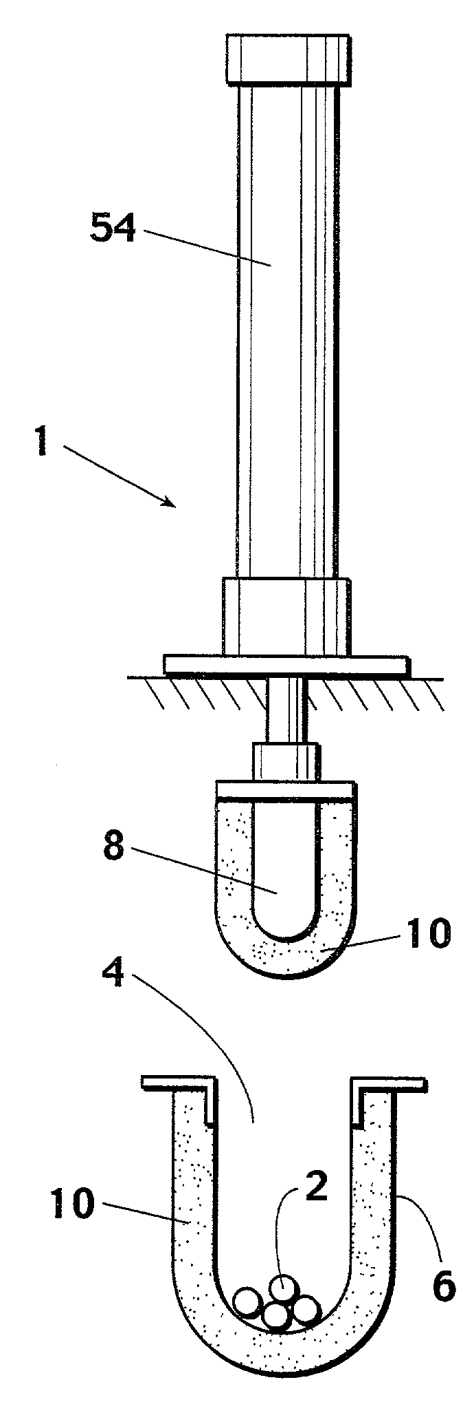
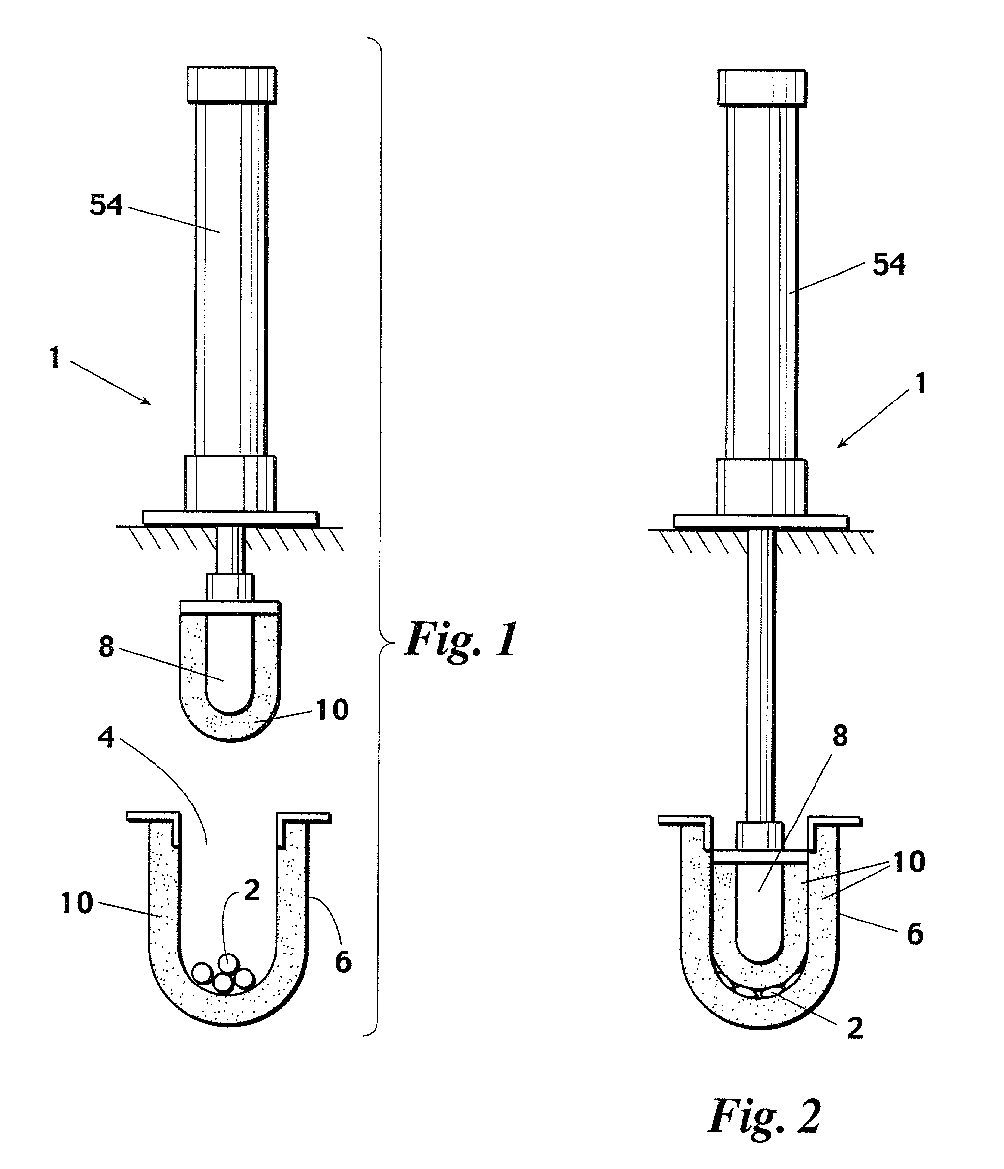
[0046]An embodiment 1 of an inventive apparatus for use in the first stage operation of the inventive method is depicted in FIGS. 1-3. Using inventive apparatus 1, the product, either food or meat 2, is brought into a compression area 4 (see FIGS. 1 and 2). This area preferably comprises two hard surfaces 6 and 8 that are covered with a thick pliable material 10. This material is selected to conform to the shape of the product 2, especially in the case of a non-homogeneous material such as a bone-in meat cut. These two surfaces preferably comprise a fixed surface 6 and a closing, movable surface 8. There is of course a force behind the movable surface such as a screw actuator, pneumatic or hydraulic cylinder, or other such mechanical device 54.

[0047]The fixed surface 6 will preferably be of a captive-type geometry, such as a “U” or “V” shaped trough, to control movement of the product. The moving surface 8 (e.g., a plunger as shown in FIGS. 1-3) will preferably have a corresponding ...

embodiment 50

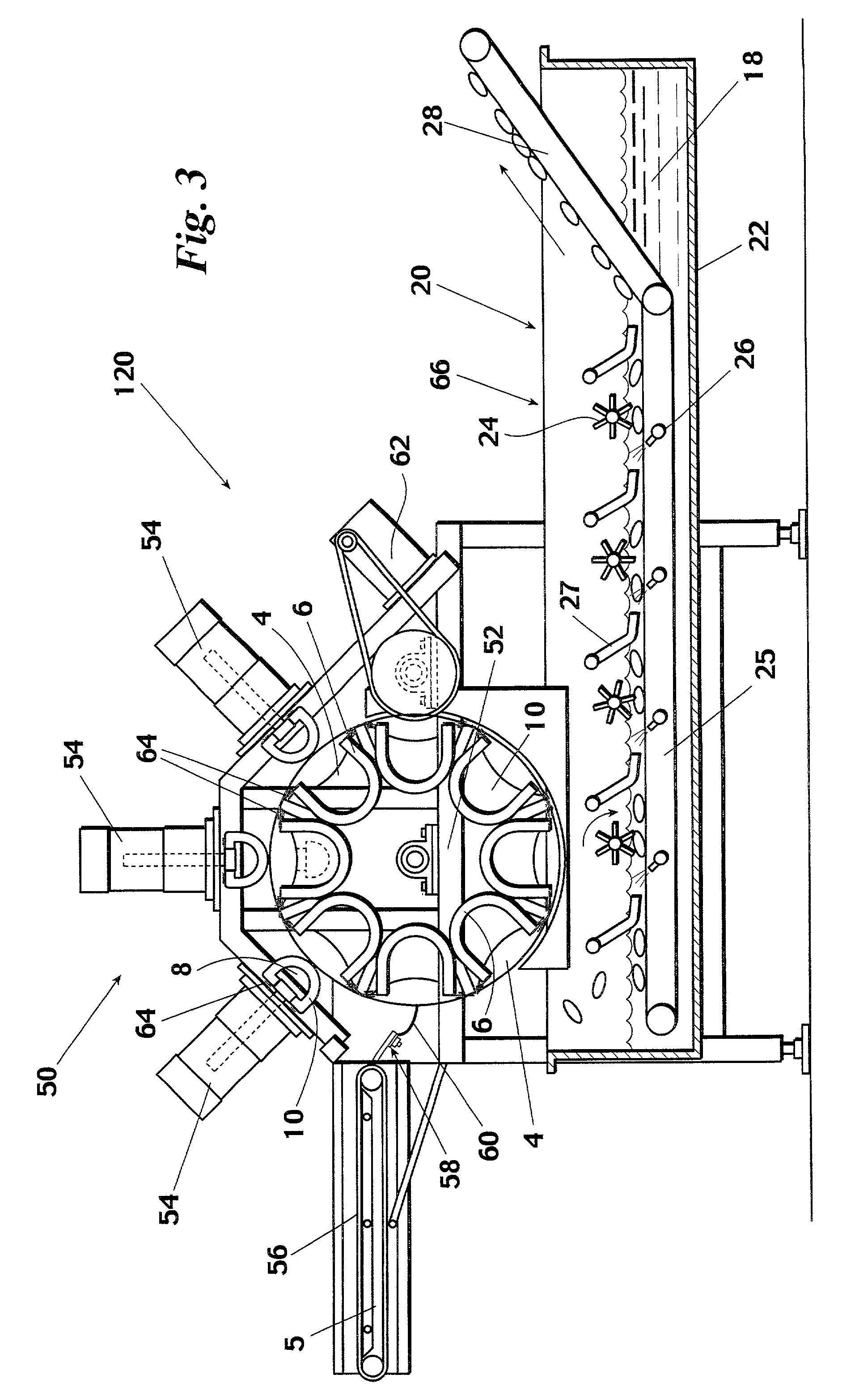
[0053]To provide continuous operation and throughput, the inventive pressing apparatus preferably comprises a plurality of pressing chambers 4 arranged in a linear or rotary fashion. An embodiment 50 of the inventive continuous apparatus is depicted in FIG. 3. Inventive apparatus 50 comprises a plurality of U-shaped pressing chambers 4 provided in a rotary bucket wheel 52. Apparatus 50 also includes a plurality of plungers 8 reciprocatingly positioned above bucket wheel 52. Plungers 8 employ mechanisms 54 for varying the pressure of the plungers 8 into cavities 4. As will be apparent to those skilled in the art, examples of suitable pressure mechanisms 54 include pneumatic or hydraulic cylinders having appropriate pressure regulators or mechanical pressing systems with associated force indicators and controls.

[0054]The inventive pressing apparatus preferably also includes: an infeed conveyor 56; a chute 58 with a flexible end piece 60 for delivering product 2 into rotating cavities ...

embodiment 150

[0061]An alternative embodiment 150 of the inventive pressing apparatus is depicted in FIGS. 8 and 9. Inventive pressing apparatus 150 is a double conveyor device which preferably comprises: a frame or other support structure 152; a lower continuous belt 154 rotatably mounted in frame 152; an upper continuous belt 156 rotatably mounted in frame 152 above lower belt 154; at least one pressing roller (preferably at least two) 158 adjustably positionable beneath and against the upper carrying run 160 of lower belt 154; at least one upper pressing roller (preferably at least two) 162 adjustably positionable above and against the lower pressing run 164 of upper belt 156; and vertical containment walls 166 positioned on each side of belts 154 and 156 for retaining product carried through inventive apparatus 150. As will be understood by those skilled in the art, inventive apparatus 150 will also include motors, belts, chains, sprockets and / or pulleys for directly or indirectly driving bel...


PUM


Abstract

A method and apparatus of treating food items having muscle protein and a product produced by the inventive apparatus and method. The inventive method preferably utilizes the inventive apparatus to (a) continuously press the food items using a pliable material which conforms to and at least partially surrounds the food items when pressing and / or (b) infuse the food items with a treatment liquid preferably by impacting the food items while they are at least partially suspended in the solution.

Description

[0001]This application claims the benefit of United States Provisional Patent Application Ser. No. 60 / 219,895, filed Jul. 21, 2000.FIELD OF THE INVENTION[0002]The present invention relates to apparatuses and methods for tenderizing and infusing muscle protein products with marinades and / or other liquids and to the products produced by such apparatuses and methods.BACKGROUND OF THE INVENTION[0003]Infusion, curing, pickling, injection and marination of meat and food substances has been in practice for many years. The initial most common method was to submerge the material in a solution of marination, pickle solution, or brine for long periods of time. This could take one or more days depending upon the level of uptake of the solution. The industry progressed from that practice to either a needle injection or a massaging method using an upright drum, filled with product and the marination solution, with an agitator. The multi-vane agitator would travel in slow rotational speed in one d...

Claims


Application Information

Patent Timeline
IPC IPC(8): A23L1/318A23L13/70A22C7/00A22C9/00
CPCA22C7/0023A22C7/0069A22C9/004A22C9/007
Inventor ANDERS, GARY H.KING, DANIEL W.
Owner AK FOOD TECH
Learn More