Method for absolute calibration of global navigation satellite system antennas

an antenna and global navigation technology, applied in the field of absolute calibration of global navigation satellite system antennas, can solve the problems of significant consistency, inaccurate absolute calibration of antennas, and inability to provide absolute phase calibration of tested antennas, etc., and achieve the effect of accurate absolute antenna calibration

Active Publication Date: 2008-06-03
TOPCON GPS
View PDF4 Cites 35 Cited by
  • Summary
  • Abstract
  • Description
  • Claims
  • Application Information

AI Technical Summary

Benefits of technology

[0013]The present invention provides an improved antenna calibration technique for accurately performing absolute antenna calibrations.
[0017]One of the advantages of antenna calibration in accordance with the present invention is that there is no need to know the precise location of either the auxiliary antenna or the antenna to be calibrated prior to the calibration process. Neither is there a need to know a precise baseline between the auxiliary antenna and the antenna to be calibrated. The double differencing between interpolated home and interpolated non-home data sets completely eliminates the data collected at the auxiliary antenna.

Problems solved by technology

However, antennas do not have single well defined phase centers, but instead the location of an antenna phase center is a function of the direction from which the antenna receives a signal.
These calibrations do not provide absolute phase calibration for the tested antennas, but rather the relative calibrations with respect to this particular reference antenna.
First, there is significant reliance on the consistency of antenna types.
Given manufacturing variations, such reliance may result in inaccurate calibrations.
Another disadvantage to both the relative and absolute methods is that the precise baseline between the reference and test antennas must be known so that variations can be determined from a study of measurement residuals after the known baseline contribution is removed.

Method used


Image

  • Method for absolute calibration of global navigation satellite system antennas
  • Method for absolute calibration of global navigation satellite system antennas
  • Method for absolute calibration of global navigation satellite system antennas

Examples


Embodiment Construction

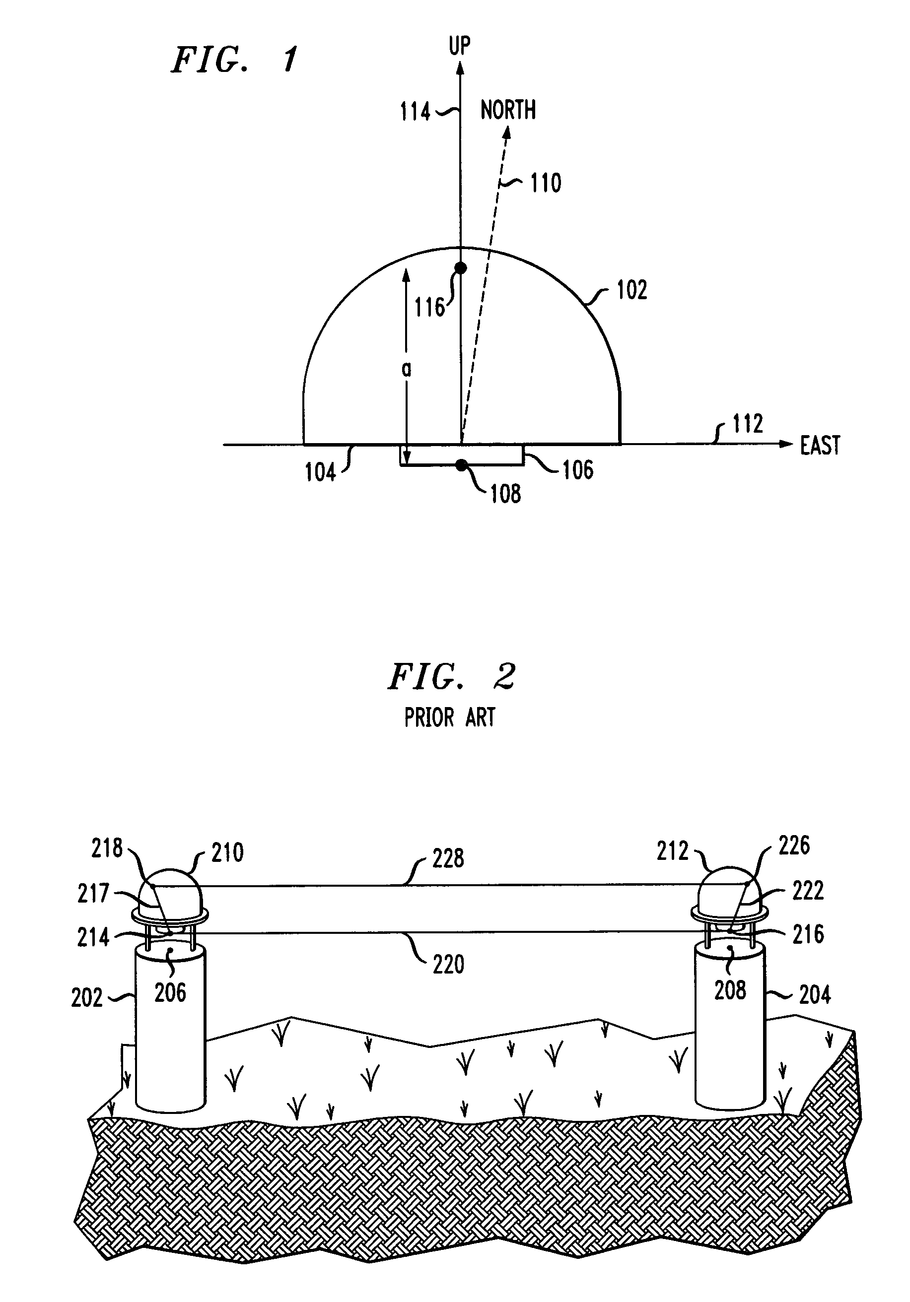
[0025]FIG. 1 shows a geometric diagram of a GPS antenna in a coordinate system. The figure shows a cross section of an antenna having a half-sphere enclosure 102, a base 104, and a low noise amplifier (LNA) 106. This type of antenna is well known in the art of GPS antennas. The antenna reference point (ARP) 108 is a known physical point on the antenna, typically located at the base of the LNA 106 as shown in FIG. 1. It is conventional to express phase center location as a triad in terms of north, east, and up coordinates, with each of the coordinates expressed in mm. This coordinate system is shown in FIG. 1 with a north axis 110, an east axis 112, and an up axis 114. Consider now that the antenna has a phase center 116 located on the up axis which is coincident with the axis of symmetry of the antenna at a distance of a mm above the ARP 108. Assuming a satellite directly overhead, the voltage front from the satellite will activate the phase center 116. Thus, relative to the ARP 108...


PUM


Abstract

Disclosed is an antenna calibration technique for performing absolute antenna calibration. An antenna to be calibrated is positioned in a first position, called a home position, and records data samples from received satellite signals. The antenna is then moved to another location, called a non-home position, and records data samples from received satellite signals while at the non-home position. The antenna is then returned to the home position and records additional data samples. During the time that the antenna to be calibrated is recording its data samples, an auxiliary antenna is also recording satellite signal data samples. The data samples taken by the antenna to be calibrated during the home and non-home positions are differenced with the data samples taken by the auxiliary antenna during the same time period. The differenced data are interpolated to determine, at a particular time, an estimate of what the differenced data would be if the antenna to be calibrated occupied both the home and non-home positions at the same point in time. This allows for determination of the phase center of the antenna to be calibrated by differencing the interpolated estimates.

Description

BACKGROUND OF THE INVENTION[0001]The present invention relates generally to antenna calibration, and more particularly to absolute calibration of global navigation satellite system antennas.[0002]Global navigation satellite systems (GNSS), such as GPS (U.S.A.) and GLONASS (Russia), are well known in the art. A navigation receiver receives and processes radio signals transmitted by satellites located within line-of-sight distance of the receivers. The satellite signals comprise carrier signals that are modulated by pseudo-random binary codes. The receiver measures the time delay of the received signal relative to a local reference clock or oscillator. These measurements enable the receiver to determine the so-called pseudo-ranges between the receiver and the satellites. The pseudo-ranges are different from the ranges (distances) between the receiver and the satellites due to various noise sources and variations in the time scales of the satellites and receiver. If the number of satel...

Claims


Application Information

Patent Timeline
Patent Type & Authority Patents(United States)
IPC IPC(8): G01S5/14G01S19/36
CPCG01S19/36
Inventor GOAD, CLYDE C.
Owner TOPCON GPS
Why Eureka
Try Eureka