
Bearing assembly comprising double injection of liquid lubricant, and aeronautical vehicle comprising at least one such assembly

a technology of liquid lubricant and bearing assembly, which is applied in the direction of machine/engine, drip or splash lubrication, transportation and packaging, etc., can solve the problems of non-negligible disadvantage, degradation of bearings that have reached critical temperature, and insufficient lubrication of conventional bearings of the periodic injection with grease type in these aeronautical vehicles, so as to achieve the effect of increasing the duration/range of the vehicl

Active Publication Date: 2008-06-10
SN DETUDE & DE CONSTR DE MOTEURS DAVIATION S N E C M A
View PDF6 Cites 20 Cited by
  • Summary
  • Abstract
  • Description
  • Claims
  • Application Information

AI Technical Summary

Benefits of technology

The dual injection system effectively maintains a stable lubricant film without increasing pressure, enhancing the endurance and range of aeronautical vehicles by reducing fuel consumption and eliminating the need for costly and heavy pumping systems.

Problems solved by technology

In a known manner, conventional lubrication of bearings of the periodic injection with grease type in these aeronautical vehicles is insufficient, due to the high performances required in this field, such as the high rotor shaft rotation speed.
In this respect, it should be noted that when lubrication is insufficient, the two phenomena mentioned above mutually exacerbate each other and possibly lead to degradation of a bearing that has reached a critical temperature.
Although this solution according to prior art is satisfactory in terms of bearing lubrication in that it can be used to obtain a separating film that will not degrade, it does have a non-negligible disadvantage.
This permanent feed technique requires the use of a large and complex closed circuit including recovery scoops, pipes, filters and a pump, which increases the global mass and the cost of the turbo-shaft engine comprising such a bearing assembly with dynamic lubrication.
Nevertheless, liquid lubricant is usually drawn off from the fuel tank on the vehicle concerned, that therefore forms the source of the non-recycled liquid lubricant.
This means that the need to set up abundant and satisfactory lubrication can possibly lead to drawing off a sufficient quantity of non-recycled fuel lubricant thus significantly reducing the endurance / range of the vehicle.
Consequently, a reduction in the fuel lubricant flow drawn off at the tank is desirable, but this can quickly result in a degradation of the thickness of the separating film between the functional surfaces of the bearing, and thus cause degradation to the bearing.

Method used


Image

  • Bearing assembly comprising double injection of liquid lubricant, and aeronautical vehicle comprising at least one such assembly
  • Bearing assembly comprising double injection of liquid lubricant, and aeronautical vehicle comprising at least one such assembly
  • Bearing assembly comprising double injection of liquid lubricant, and aeronautical vehicle comprising at least one such assembly

Examples


Embodiment Construction

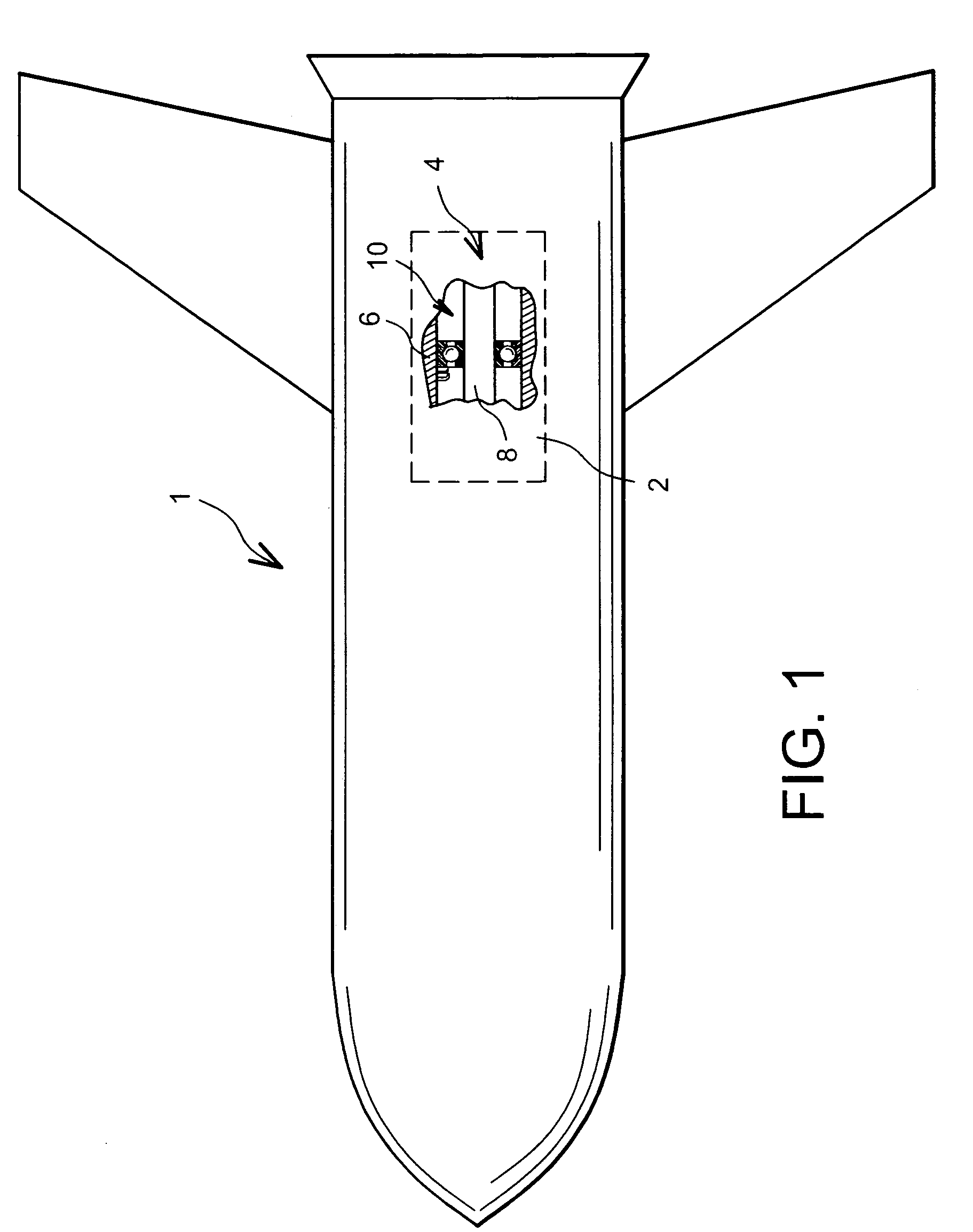
[0038]With reference firstly to FIG. 1, the figure shows a missile 1 equipped with a turbo-shaft engine 2 for its propulsion, this turbo-shaft engine 2 for example being a turbojet.

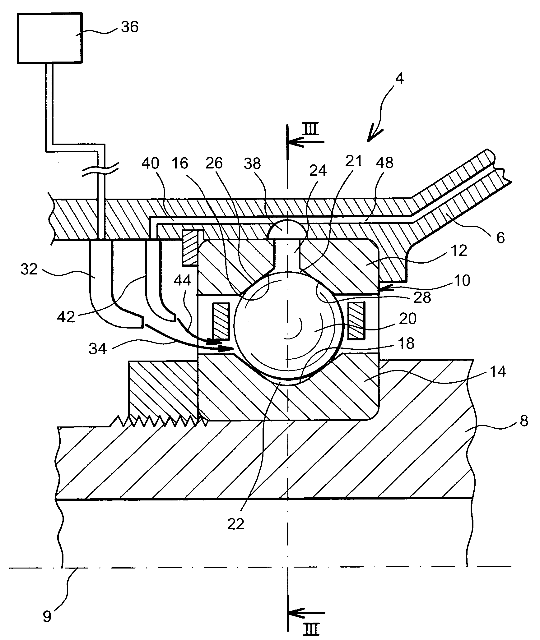
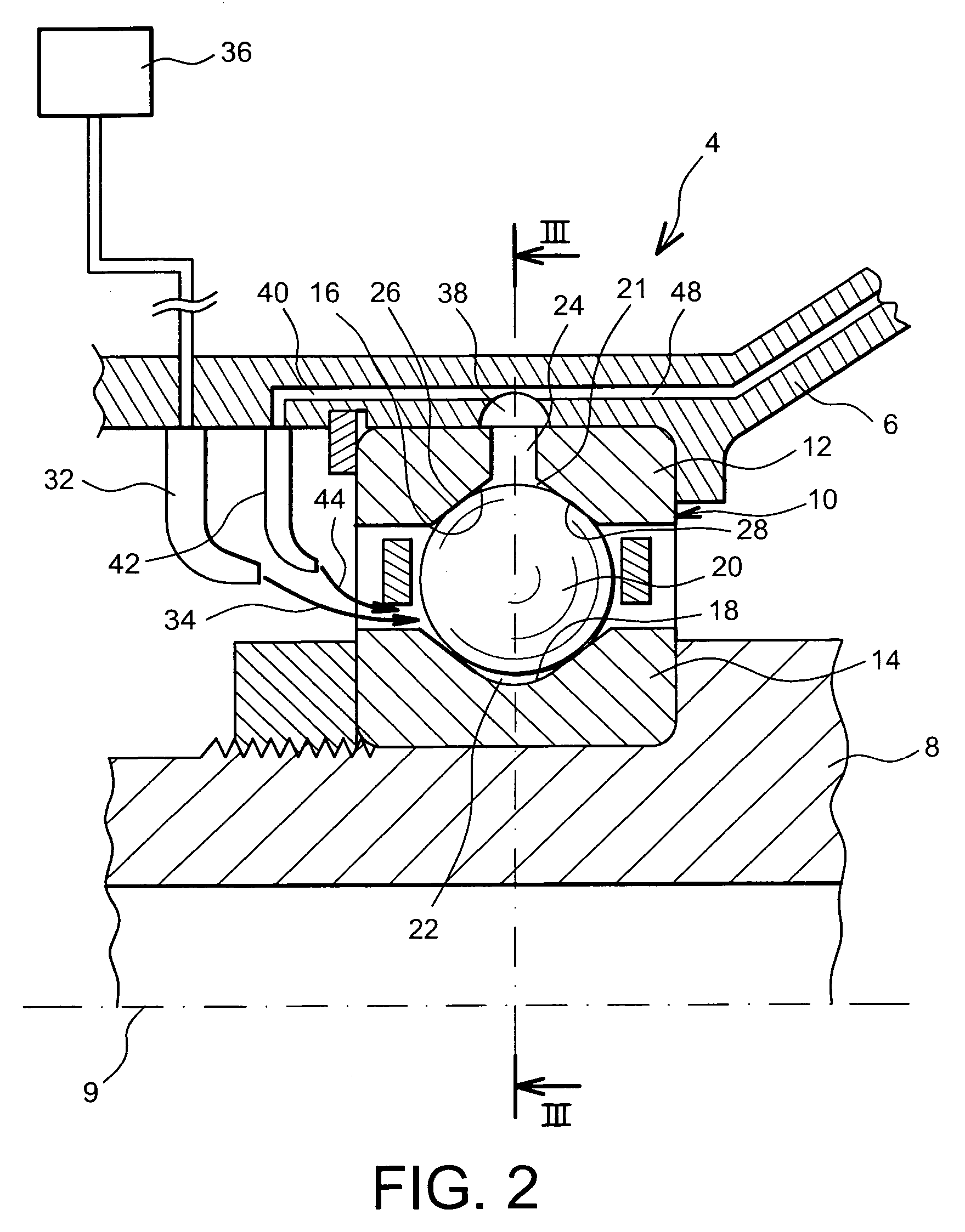
[0039]This missile 4, another object of this invention, integrates a bearing assembly 4 according to a first preferred embodiment of this invention, this assembly 4 globally comprising a case 6 of the turbo-shaft engine 2, and a rotor shaft 8 coupled to the case 6 through a lubricated bearing 10, the elements 6 and 8 being called the fixed and rotating parts respectively in the remainder of this description.

[0040]It should be noted that although the preferred application described in this disclosure relates to a missile, it should obviously be understood that the bearing assembly 4 according to the invention can be applied to all aeronautical or non-aeronautical vehicles for which the bearing concerned will be lubricated at least partly by a source of non-recycled liquid lubricant such as the fuel tank on...


PUM


Abstract

A bearing assembly includes a first liquid lubricant injector designed to be fed exclusively with non-recycled liquid lubricant to lubricate a bearing. A plurality of drain orifices passes through a bearing ring fixed to a fixed part, and the assembly also includes a second liquid lubricant injector fed with liquid lubricant drained through a collection device for collecting liquid lubricant drained from the orifices, the collection device communicating firstly with a reinjection circuit connected to the second injector, and with a bypass circuit designed to evacuate surplus drained liquid lubricant.

Description

TECHNICAL DOMAIN[0001]This invention relates generally to a bearing assembly comprising a fixed part, a rotating part and a bearing inserted between these fixed and rotating parts, the assembly also comprising a first liquid lubricant injector fed exclusively by a non-recycled liquid lubricant source, such as a missile fuel tank.[0002]The invention also relates to any aeronautical vehicle equipped with a turbo-shaft engine for its propulsion, including at least one such bearing assembly.STATE OF PRIOR ART[0003]Each turbo-shaft engine on aeronautical vehicles such as a missile equipped with one or several turbo-shaft engines integrates at least one bearing assembly globally comprising a rotor shaft, a stator, and a bearing inserted between the rotor shaft and the stator.[0004]In this very widespread type of assembly, the liquid lubricant is transported inside the bearing so as to wet the functional surfaces of the bearing, and therefore to renew the liquid film and to collect heat ge...

Claims


Application Information

Patent Timeline
Patent Type & Authority Patents(United States)
IPC IPC(8): F16C19/00F16C33/66
CPCF16C33/58F16C33/6685F16C33/6659F16C19/166F16C19/26F16C2360/00F16C2326/43
Inventor PLONA, DANIEL GEORGES
Owner SN DETUDE & DE CONSTR DE MOTEURS DAVIATION S N E C M A
Learn More