
DRAM device and method of manufacturing the same

a dram and memory technology, applied in solid-state devices, sewer cleaning, sewer pipelines, etc., can solve the problems of reducing the operation and reducing the efficiency of the dram device, so as to improve the operation efficiency and reduce the influence. , the effect of minimizing the influen

Inactive Publication Date: 2008-06-10
SAMSUNG ELECTRONICS CO LTD
View PDF11 Cites 4 Cited by
  • Summary
  • Abstract
  • Description
  • Claims
  • Application Information

AI Technical Summary

Benefits of technology

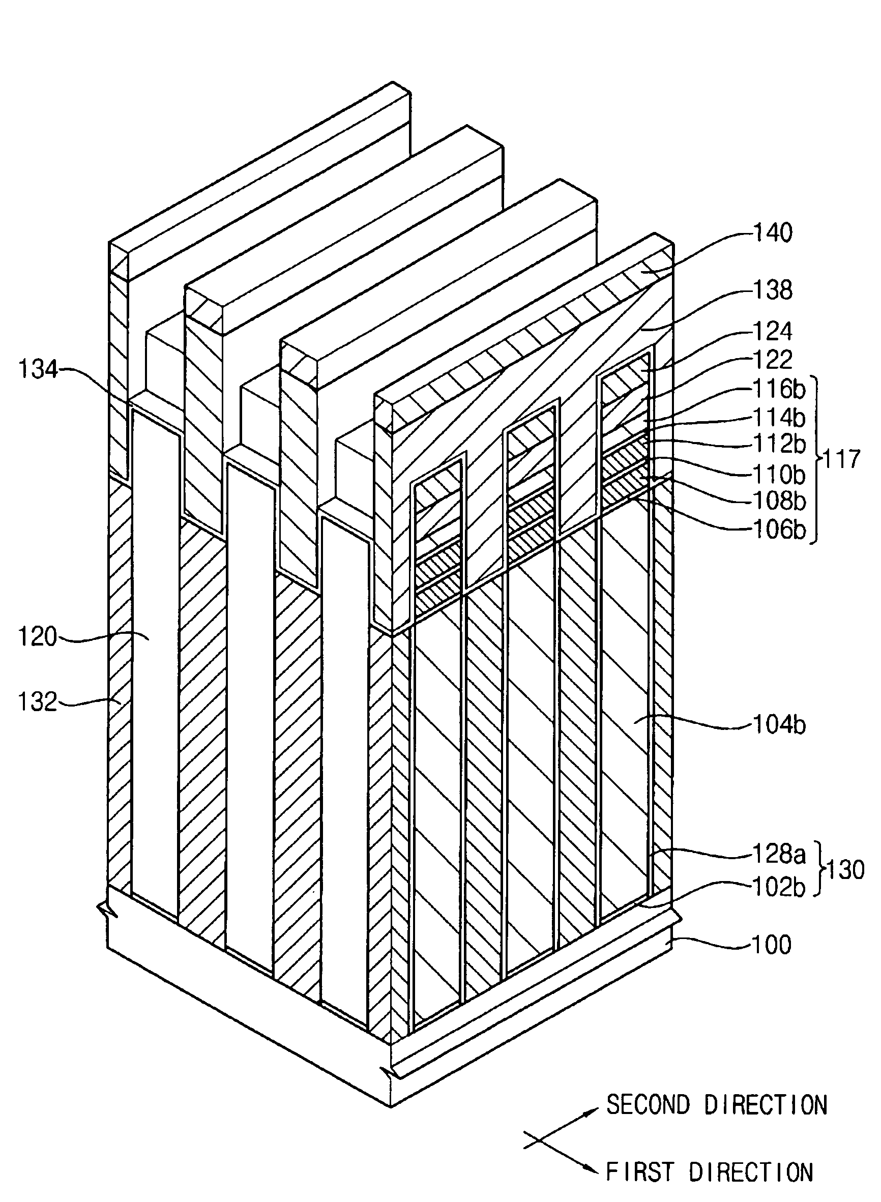
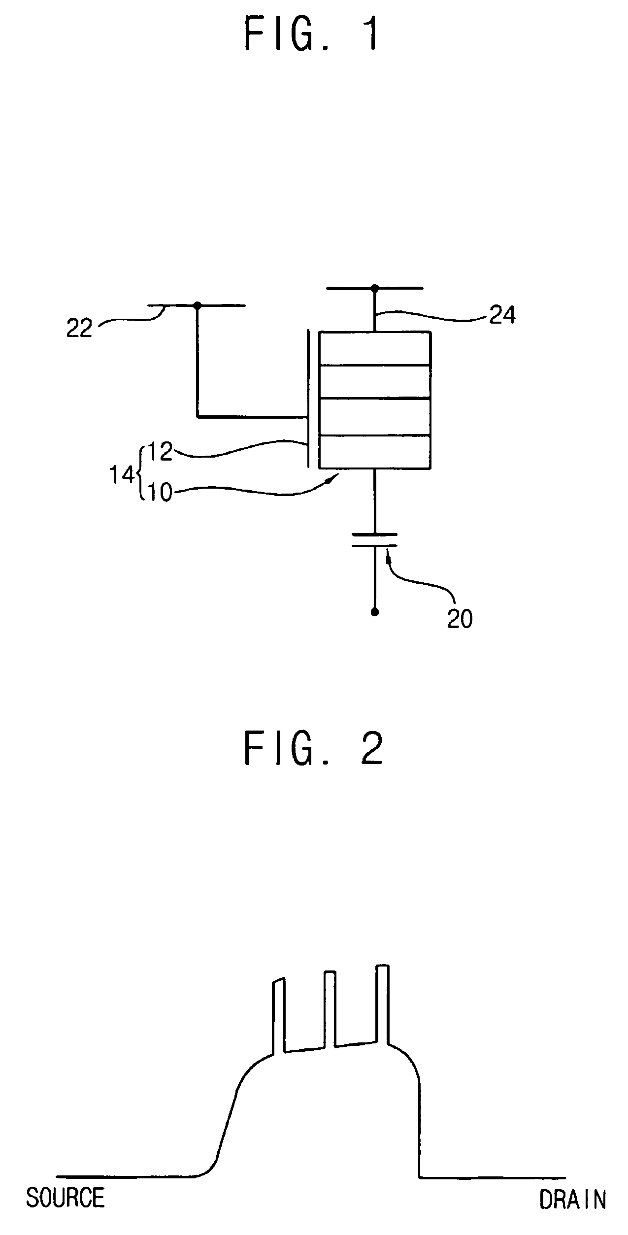
The present invention provides a highly integrated DRAM device with a multiple tunnel junction (MTJ) structure that includes a bit line, a word line, and a capacitor. The MTJ structure includes conductive patterns and nonconductive patterns alternately stacked on each other. The nonconductive patterns have a band gap larger than the conductive patterns and the word line faces the sidewall of the MTJ structure. The method of manufacturing the DRAM device includes forming a preliminary storage electrode, a preliminary MTJ structure, a conductive layer, a dielectric layer, a plate electrode, and a word line. The technical effects of the present invention include higher integration, improved performance, and reduced power consumption.

Problems solved by technology

Accordingly, when a design rule for a DRAM device is no more than about 100 nm, the DRAM device is frequently influenced by a short channel effect, which may generate an operation failure in the DRAM device.
Because of the accurate aligning process, obtaining an area of 4F2 (wherein, F indicates a critical dimension of the DRAM) for a DRAM is difficult.
Vertically stacking a pass transistor on a silicon substrate or silicon epitaxial layer may be difficult.
Accordingly, vertically stacking a unit cell of a conventional DRAM on a substrate to form a multilayer structure is difficult.
For at least the above reasons, increasing an integration degree of conventional DRAM devices has been difficult.

Method used


Image

  • DRAM device and method of manufacturing the same
  • DRAM device and method of manufacturing the same
  • DRAM device and method of manufacturing the same

Examples


Embodiment Construction

[0030]The invention is described more fully hereinafter with reference to the accompanying drawings, in which embodiments of the invention are shown. This invention may, however, be embodied in many different forms and should not be construed as limited to the embodiments set forth herein. Rather, these embodiments are provided so that this disclosure will be thorough and complete, and will fully convey the scope of the invention to those skilled in the art. In the drawings, the size and relative sizes of layers and regions may be exaggerated for clarity.

[0031]It will be understood that when an element or layer is referred to as being “on”, “connected to” or “coupled to” another element or layer, it can be directly on, connected or coupled to the other element or layer or intervening elements or layers may be present. In contrast, when an element is referred to as being “directly on,”“directly connected to” or “directly coupled to” another element or layer, there are no intervening ...


PUM


Abstract

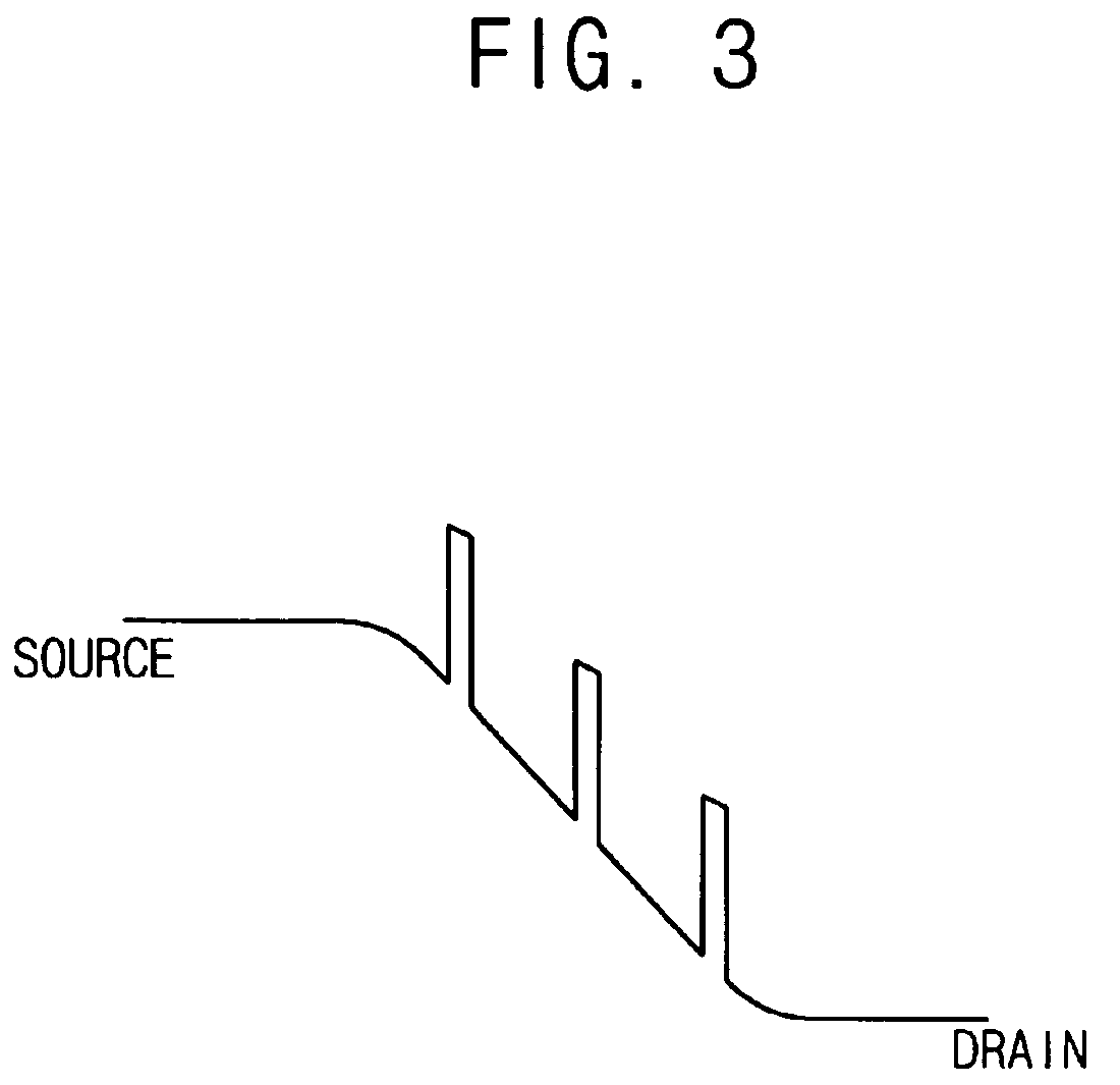
In a DRAM device and a method of manufacturing the same, a multiple tunnel junction (MTJ) structure is provided, which includes conductive patterns and nonconductive patterns alternately stacked on each other. The nonconductive patterns have a band gap larger than a band gap of the conductive patterns. A gate insulation layer and a gate electrode are formed on a sidewall of the MTJ structure. A word line is connected with the MTJ structure, and a bit line is connected with one of top and bottom surfaces of the MTJ structure. A capacitor is connected with one of top and bottom surfaces of the MTJ structure that is not connected with the bit line. Current leakage in the DRAM device is reduced and a unit cells may be vertically stacked on the substrate, so a smaller surface area of the substrate is required for the DRAM device.

Description

PRIORITY STATEMENT[0001]This application claims the benefit of priority to Korean Patent Application No. 2005-18405 filed on Mar. 5, 2005, the entire contents of which is herein incorporated by reference.BACKGROUND OF THE INVENTION[0002]1. Field of the Invention[0003]Example embodiment of the present invention relate to a dynamic random access memory (DRAM) device and a method of manufacturing the same, and more particularly to an integrated DRAM device and a method of manufacturing the same.[0004]2. Description of the Related Art[0005]Conventionally, a unit cell of a DRAM device may include one pass transistor and one capacitor that may be electrically connected in series. A pass transistor may control the movement of electrons into and / or out of a device, thereby functioning as a switching element controlling whether electrons are accumulated in or charged from a capacitor. Data may be stored and / or erased in a DRAM device when electrons are accumulated into or charged from a capa...

Claims


Application Information

Patent Timeline
Patent Type & Authority Patents(United States)
IPC IPC(8): H01L21/8244H01L21/8234H10B12/00H10B10/00
CPCH01L27/10829H01L27/10873H10B12/37H10B12/05E03F3/046E03F9/00
Inventor YOON, HONG-SIKYEO, IN-SEOKBAIK, SEUNG-JAEHUO, ZONG-LIANGKIM, SHI-EUN
Owner SAMSUNG ELECTRONICS CO LTD
Learn More