Authentication protocol using a multi-factor asymmetric key pair

a multi-factor asymmetric key pair and authentication protocol technology, applied in the field of cryptosystems, can solve the problems of eve being able to potentially eavesdrop, simple schemes suffer, and old problems such as access control

Active Publication Date: 2008-06-10
VMWARE INC
View PDF12 Cites 54 Cited by
  • Summary
  • Abstract
  • Description
  • Claims
  • Application Information

AI Technical Summary

Problems solved by technology

Access control is an old problem, tracing its roots to the earliest days of computers.
This simple scheme suffers from two problems.
A second problem with this approach is that when Alice enters her password it travels from her terminal to the computer in the clear, and Eve could potentially eavesdrop.
In this example as F( ) is a one way function, computing XD45DTY from apple23 is easy, but as it is a “one way function”, the reverse is believed to be computationally difficult or close to impossible.
However, this approach, while solving the problems due to the storage of the password on the computer, does not solve the problem of the password traveling in the clear.
The passwords are transmitted in the clear, thus token techniques are subject to man-in-the-middle attacks.
As will be recognized by one of ordinary skill, this particular approach is undesirable due to it being susceptible to a dictionary attack, to be discussed in detail further below.
Smart card techniques are associated with certain problems.
These problems include the fact that the technique is costly to implement, due to hardware costs.
Further, a lack of readers makes use of a user's smart card difficult, and smart cards themselves are subject to loss.
An attacker who does not know K, and sees C, cannot successfully decrypt the message, if the underlying algorithms are strong.
Symmetric key systems have always suffered from a major problem—namely how to perform key distribution.
This is simply because in practice all known asymmetric systems are fairly inefficient, and while they are perfectly useful for encrypting short strings such as K, they are inefficient for large messages.
With digital signatures this is not possible since only the sender has knowledge of the sender's private key required to compute the signature.
The verifier can only verify the signature but not generate it.
The process for getting and storing the binding [Alice, Ealice] which binds Ealice to Alice is tricky.
Asymmetric key cryptosystems have been around for a long time, but have found limited use.
The primary reasons are twofold: (a) the private key D in most systems is long, which means that users cannot remember them, and they have to either be stored on every computer they use, or carried around on smart cards or other media; and (b) the infrastructure for ensuring a certificate is valid, which is critical, is cumbersome to build, operate, and use.
This clearly does not scale well to an environment with millions of users.
The second method proposed was to require that one inquire about the validity of a certificate on-line, which has its own associated problems.
Further, if the server is informed that a particular ID has been revoked, then it will cease to perform its part of the operation for that user, and consequently no further signatures can ever be performed.
The converse function in SSL, client side SSL, which lets a client authenticate herself to a server by means of a digital signature is rarely used, because although the technical mechanism is much the same, it now requires users to manage certificates and long private keys which has proven to be difficult, unless they use the split private key system.
Although the attacker did not gain access, now legitimate users cannot access their own accounts either, creating a denial of service problem.
The system is only vulnerable to this attack if it is true that M has some predictable structure.
Further, and as discussed above, existing multiple factor systems that overcome these problems rely upon expensive hardware.
Because of this and other reasons, such systems have failed to gain support.

Method used


Image

  • Authentication protocol using a multi-factor asymmetric key pair
  • Authentication protocol using a multi-factor asymmetric key pair
  • Authentication protocol using a multi-factor asymmetric key pair

Examples


Embodiment Construction

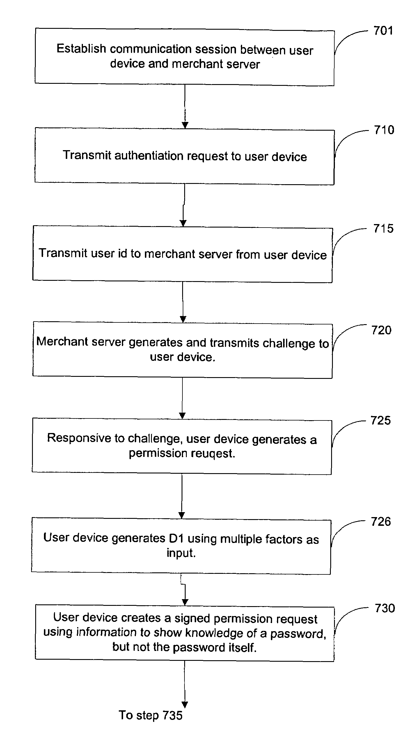
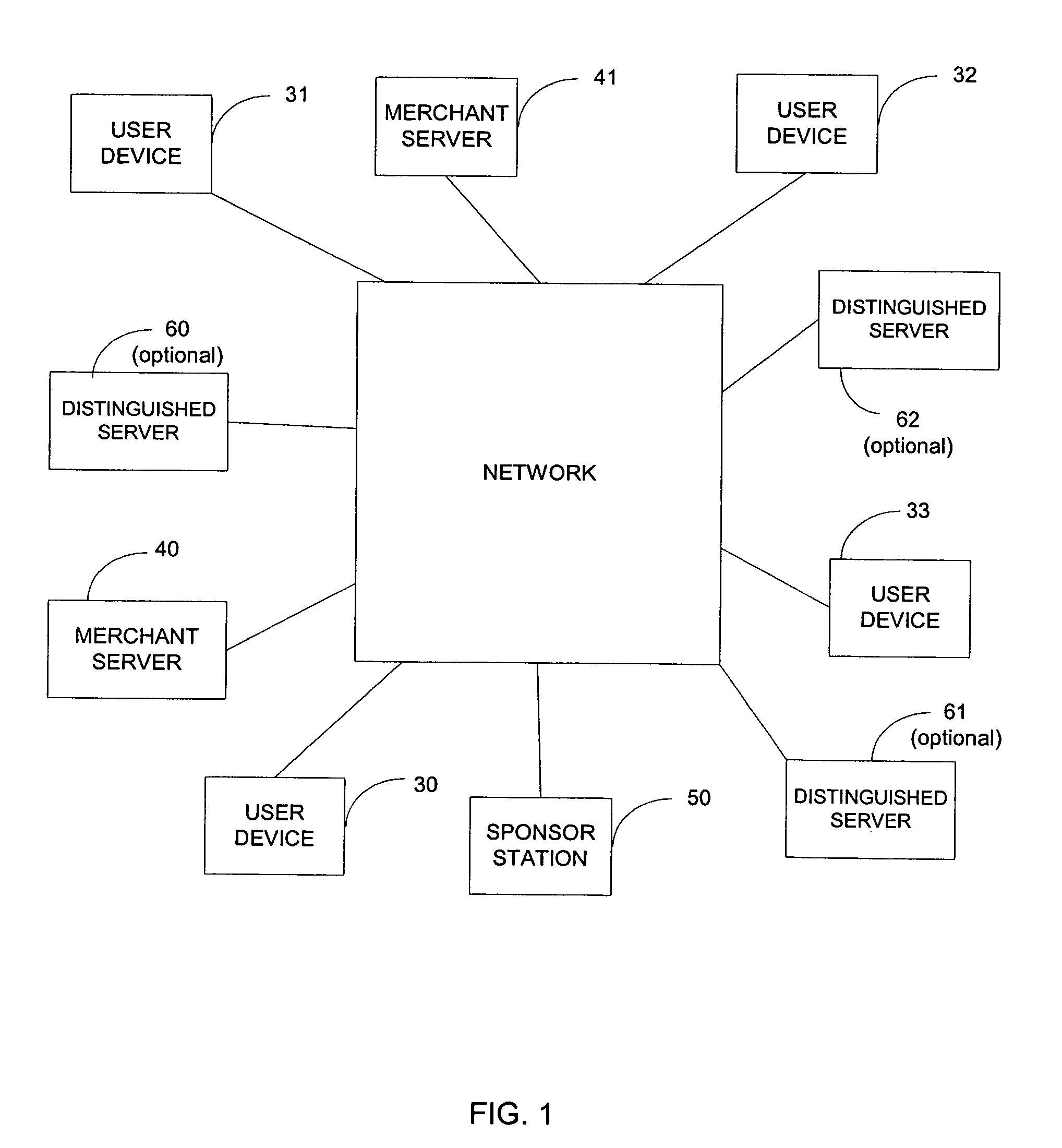
[0053]FIG. 1 illustrates a network 10, which could be the Internet. As shown, the network 10 is an interconnection of networked devices in communication with each other. These networked devices include networked devices 30-33 associated with individual network users, networked devices 40-41 associated with merchant network users, a sponsor station 50 associated with a sponsor, and optional networked devices 60-62 associated with entities known to and trusted by the sponsor.

[0054]Networked devices 30-33 will be referred to as user devices. These network devices are typically personal computers, but could be other type network devices. Networked devices 40-41 will be referred to as merchant servers. It should be understood that merchant servers 40-41 could be associated with any type entity having a presence on network 10. Optional networked devices 60-62 will be referred to as distinguished servers. It will be understood that a network may consist of more networked devices than depic...


PUM


Abstract

Techniques for user authentication based upon an asymmetric key pair having a public key and a split private key are provided. A first portion of the split private key is generated based upon multiple factors under control of the user. The factors include a password. A challenge is cryptographically combined with a first one of the multiple factors, but not the user password, to form a first message. The first message is transformed with the generated first portion to form a second message, which is then sent to an authentication entity. The sent second message is transformed to authenticate the user by proving direct verification of user control of the first factor.

Description

RELATED APPLICATIONS[0001]This application is related to U.S. application Ser. No. 11 / 055,987, filed concurrently herewith, and entitled “ARCHITECTURE FOR ASYMMETRIC CRYPTO-KEY STORAGE”, U.S. application Ser. No. 11 / 055,986, filed concurrently herewith, and entitled “TECHNIQUE FOR ASYMMERIC CRYPTO-KEY GENERATION”, U.S. application Ser. No. 11 / 056,120, filed concurrently herewith, and entitled “MULTIPLE FACTOR PRIVATE PORTION OF AN ASYMMETRIC KEY”, U.S. application Ser. No. 11 / 056,116, filed concurrently herewith, and entitled “ROAMING UTILIZING AN ASYMMETRIC KEY PAIR”, U.S. application Ser. No. 11 / 056,114, filed concurrently herewith, and entitled “ASYMMETRIC KEY PAIR HAVING A KIOSK MODE”, and U.S. application Ser. No. 11 / 056,115, filed concurrently herewith, and entitled “TECHNIQUE FOR PROVIDING MULTIPLE LEVELS OF SECURITY”. This application is also related to U.S. application Ser. No. 09 / 739,260, filed Dec. 19, 2000, and entitled “SYSTEM AND METHOD FOR CRYPTO-KEY GENERATION AND US...

Claims


Application Information

Patent Timeline
Patent Type & Authority Patents(United States)
IPC IPC(8): H04L9/00
CPCH04L9/3271H04L9/085
Inventor SANDHU, RAVINDERPAL SINGHSCHOPPERT, BRETT JASONGANESAN, RAVIBELLARE, MIHIRDESA, COLIN JOSEPH
Owner VMWARE INC
Why Eureka
Try Eureka