
Pathway light fixture with interchangeable components

a technology of interchangeable components and light fixtures, which is applied in the direction of fixed installations, lighting and heating equipment, and ways, etc., can solve the problems of accelerating deterioration, and affecting the light outpu

Active Publication Date: 2008-06-17
HUNTER INDUSTRIES
View PDF39 Cites 56 Cited by
  • Summary
  • Abstract
  • Description
  • Claims
  • Application Information

AI Technical Summary

Benefits of technology

[0008]It is an advantage of the present invention to provide a pathway light fixture that has a moisture-proof seal to fully enclose the lamp and to protect the lamp and socket against exposure to contaminants.
[0009]Another advantage of the present invention is to provide a pathway light fixture that allows for replacement of individual components.
[0010]A further advantage of the present invention is to provide a pathway light fixture that provides for changing its appearance without requiring replacement of the entire fixture.
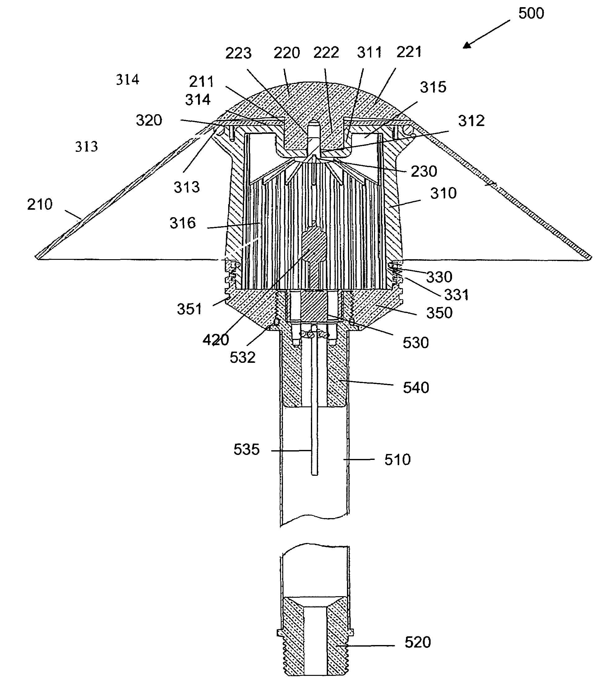
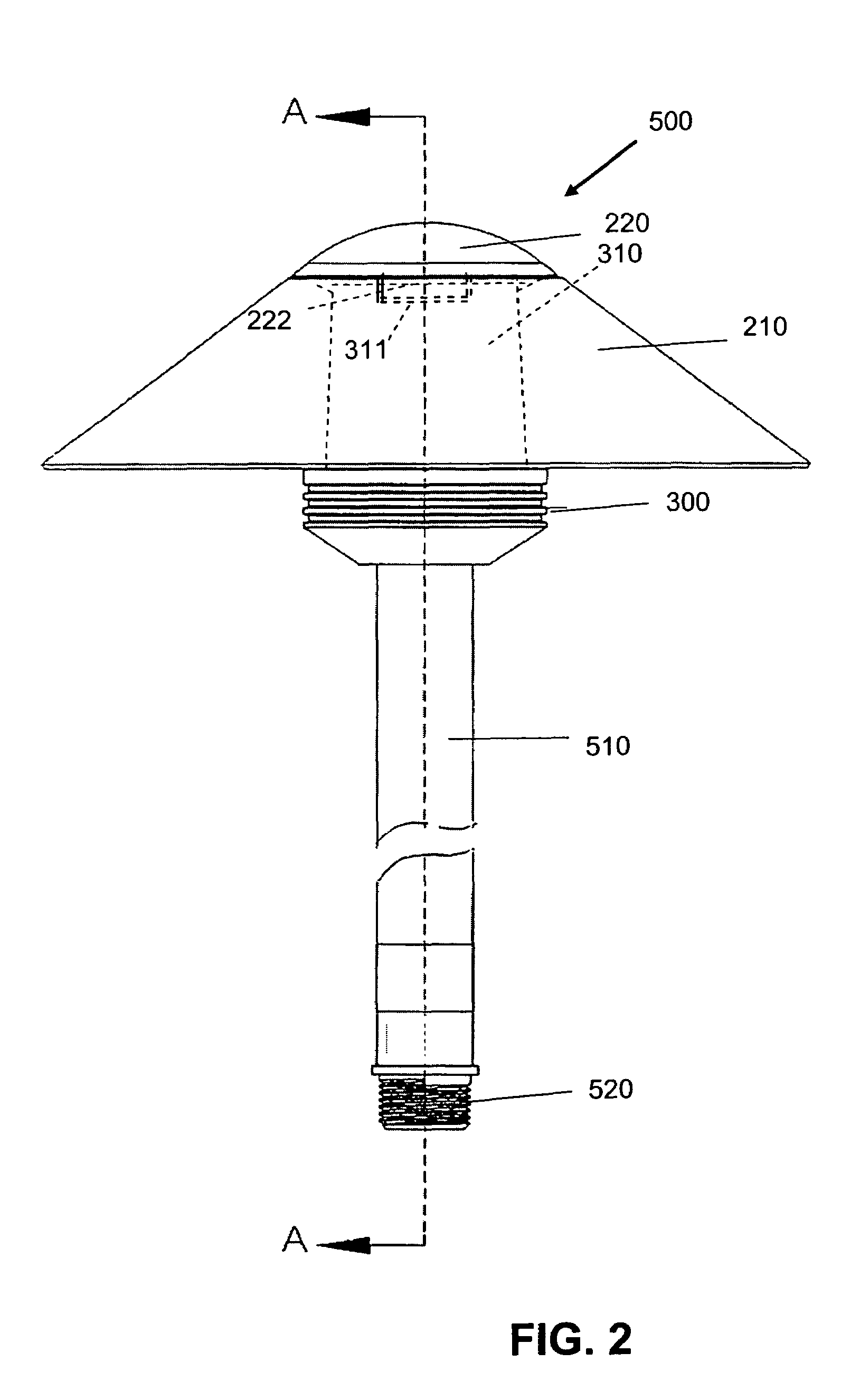
[0011]In an exemplary embodiment, the pathway downlight fixture for outdoor installation comprises a post, a socket assembly retained within the top of the stem for retaining a lamp, a lens assembly including a lens support and diffuser lens disposed on top of the stem surrounding the top of the socket assembly, and a hood assembly comprising a hood and reflector retaining cap removably mounted on top of the lens assembly.
[0012]The reflector hood is centered over the diffuser lens and flared to capture and reflect light emitted through the lens in a downward direction. The radial center of the hood has a flattened area so that the hood sits level on the top of the cylindrical lens. The center of the flattened top area has an opening therethrough to permit the base portion of the reflector retaining cap to pass through the hood and into a recess in the upper surface of the lens. An opening is formed in the center of the recess for insertion of a fastener to releasably attach the retaining cap to the lens assembly. An O-ring at the top of the lens forms a water-tight seal between the lens and the lower surface of the hood.
[0013]In the exemplary embodiment, the socket assembly includes a generally cylindrical socket housing that has a lower portion adapted to fit and be retained within the upper end of the hollow post. In one embodiment, the upper portion is threaded to mate with a threaded recess in the lens support. To provide a watertight seal, an O-ring is disposed between the lens support and the socket housing. In an alternate embodiment, the upper portion of the socket housing has at least two O-ring seats for receiving O-rings to provide an interference fit within the recess in the lower portion of the lens support.

Problems solved by technology

Outdoor light fixtures are prone to dirt build-up and / or corrosion that can diminish light output and accelerate deterioration and, ultimately, failure of the fixture.
A drawback of the closed fixture designs is that one must disassemble the housing by separating the lens from a base portion to access the lamp for replacement.
Another issue with closed fixtures is that the lens can break or crack.
In addition to being costly to replace both the lens and metal hood, introduction of a new hood into an established lighting system can detract from the aesthetics of the system since the new hood will not match the other fixtures because is has not weathered or oxidized, for example, to a verde finish in the case of copper.
Another drawback of current commercially available outdoor lighting systems is that such systems will remain in place for years.
Due to the expense and effort of replacing an entire set of fixtures, the property owner will keep the same fixtures, even if they would prefer a change in appearance, for example, if the landscape design has changed, or the house or other building has been remodeled or painted a different color.

Method used


Image

  • Pathway light fixture with interchangeable components
  • Pathway light fixture with interchangeable components
  • Pathway light fixture with interchangeable components

Examples


Embodiment Construction

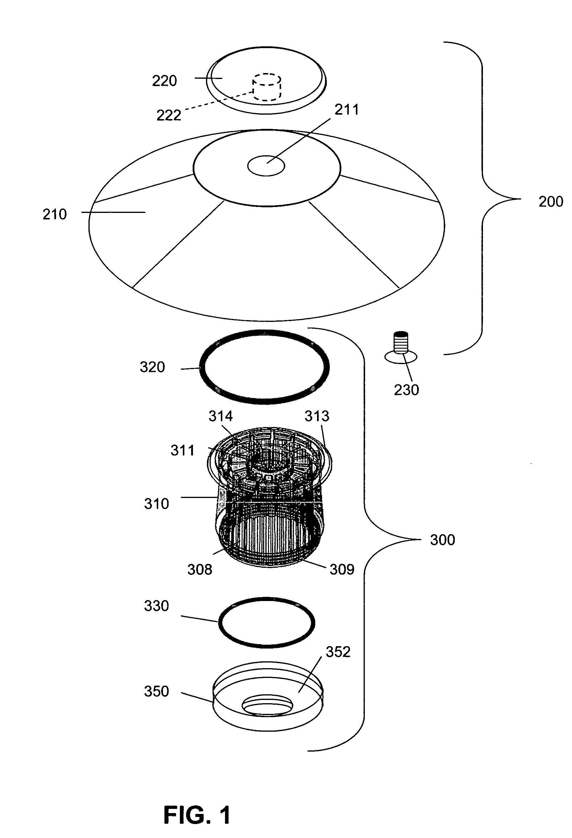
[0022]FIG. 1 illustrates reflector assembly 200 and lens assembly 300. Reflector assembly 200 includes a reflector hood 210 and a reflector retaining cap 220. Lens assembly 300 is made up of a diffuser lens 310, a top O-ring 320, a bottom O-ring 330, and a lens support 350.

[0023]Reflector hood 210 extends radially outward and down relative to diffuser lens 310 to capture and reflect downward the light emitted through diffuser lens 310. At the radial center of the hood is flattened area 212, which has a diameter that generally matches the diameter of lens 310 to allow hood 210 to sit level on top of lens assembly 300. Opening 211 is formed in the center of flattened area 212 to allow insertion of a fastener as described below.

[0024]The shape of reflector hood 210 can be varied as long as the general shape is capable of providing an effective down-reflector. Exemplary shapes are provided in FIGS. 4a-4d, and 5, showing that the hood can be pyramidal, either three-sided, as in FIG. 4b, ...


PUM


Abstract

A light fixture for use in low voltage outdoor lighting systems includes a lens assembly with a diffuser lens disposed on top of a lens support, a reflector hood and a mushroom-shaped reflector retaining cap removably mounted on top of the lens assembly. A socket and lamp extend through an opening in the lens support. The radial center of the hood has a flattened area that sits level on top of the cylindrical lens and has an opening through which a base portion of the retaining cap is inserted. A recess in the top of the lens has an opening at its bottom for receiving the base of the retainer cap which is attached with a fastener inserted through the top of the lens. An O-ring seals the lens to the lower surface of the hood and the lens and lens support are sealed to provide a water-resistant seal around the lamp. The lens support is attached to the top of a mounting post.

Description

FIELD OF THE INVENTION[0001]The invention relates to a light fixture for use in low voltage outdoor lighting systems and more specifically to a pathway light fixture with components that are easily removed and replaced.BACKGROUND OF THE INVENTION[0002]Environmental lighting, particularly outdoor lighting, is well known in commercial or public settings, such as parks and schools. Such lighting is also popular in residential applications, both to enhance the appearance and safety of the outdoor area and for security, to illuminate dark areas around a building or in a yard which may provide hiding places and unobserved entry points for intruders.[0003]Landscape and outdoor lighting systems include one or more lighting fixtures which are connected to either a 12 V transformer or a standard 120 V AC line. Some lighting fixtures enclose a halogen lamp or conventional bulb within a housing, and include a reflector assembly and a lens or window within the housing. These fixtures may be used...

Claims


Application Information

Patent Timeline
Patent Type & Authority Patents(United States)
IPC IPC(8): F21S8/00E01F9/00F21S8/08F21V11/00F21V3/00F21V5/00F21V7/00
CPCF21S8/081F21V13/04F21W2111/02F21W2121/004F21W2131/10
Inventor BEADLE, JOSHUA Z.
Owner HUNTER INDUSTRIES
Learn More