
Enhanced processing circuit for spectrometry system and spectrometry system using same

a processing circuit and spectrometry technology, applied in the field of enhanced processing circuits for spectrometry systems and spectrometry systems, can solve the problems of difficult to maintain a homogeneous field, difficult to obtain high quality spectrometry, and inconvenient operation of amplifiers for this function

Active Publication Date: 2008-06-17
COMMISSARIAT A LENERGIE ATOMIQUE ET AUX ENERGIES ALTERNATIVES
View PDF8 Cites 14 Cited by
  • Summary
  • Abstract
  • Description
  • Claims
  • Application Information

AI Technical Summary

Benefits of technology

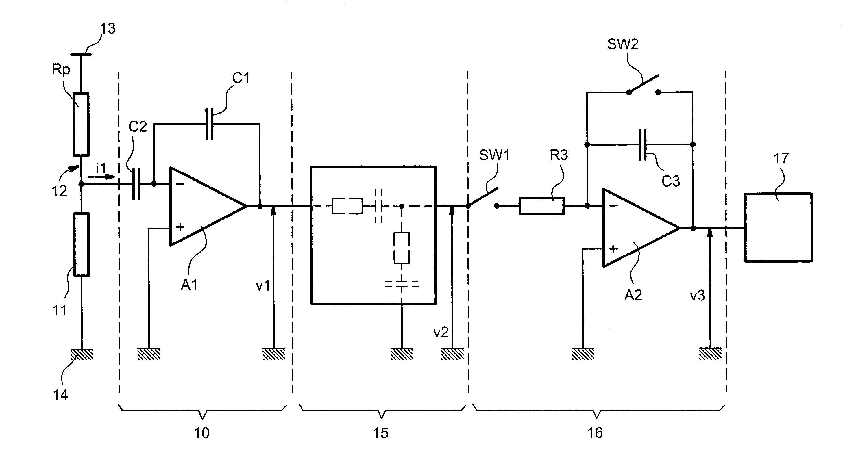
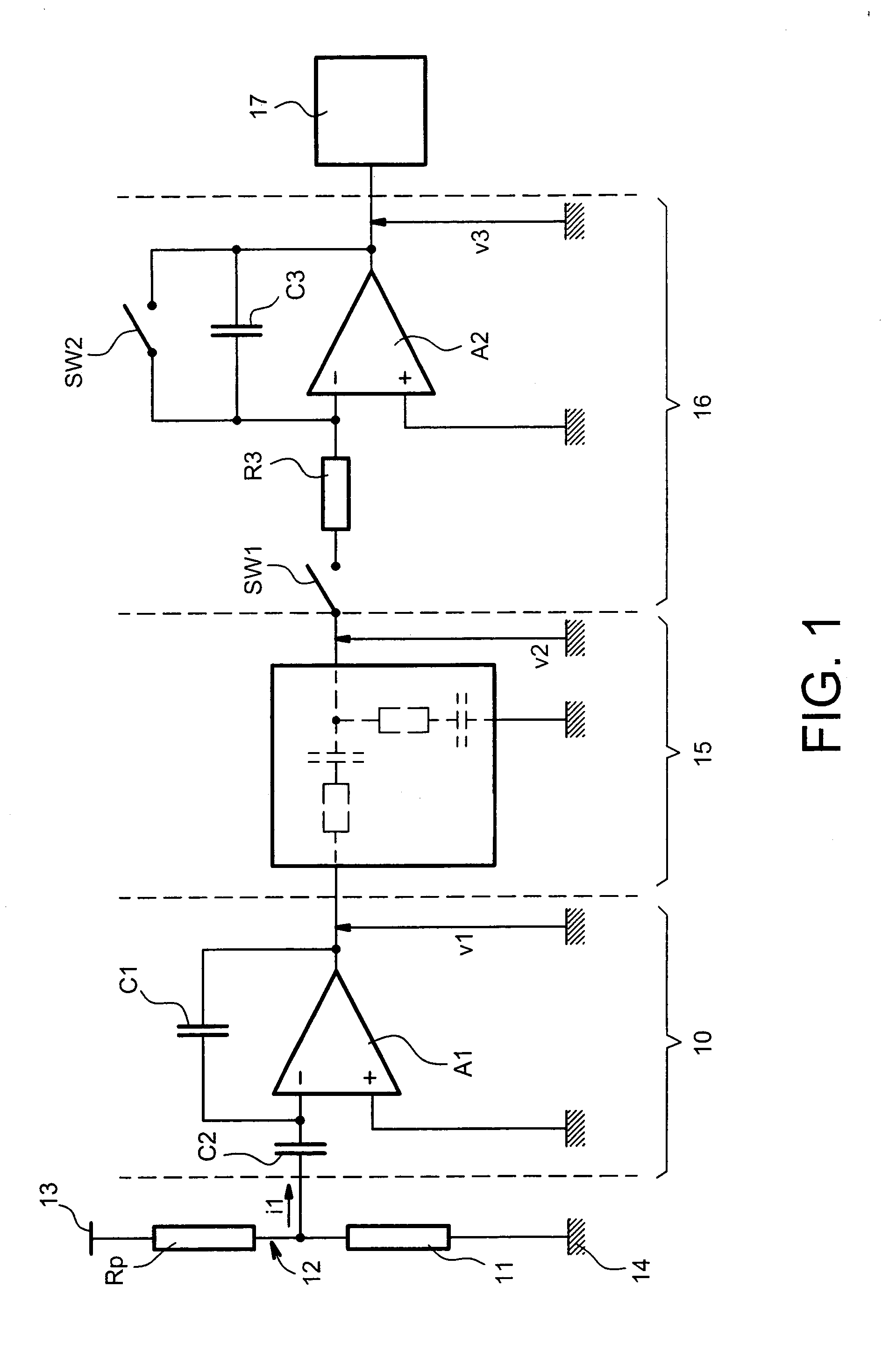
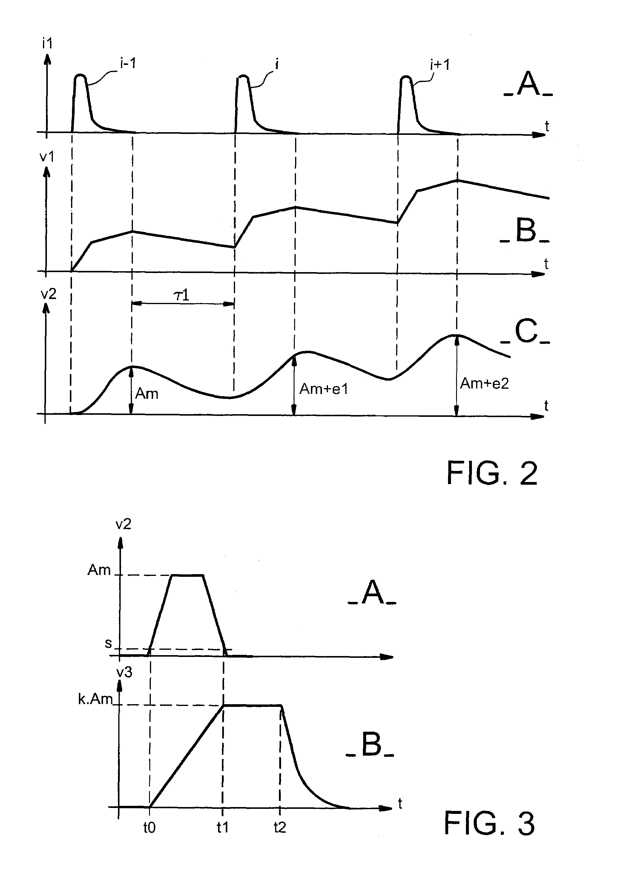
The present invention proposes a processing circuit for a spectrometry chain that overcomes the limitations and difficulties caused by the pulse filter. The circuit includes a charge preamplifier stage, an integrator stage, and a differentiator stage. The differentiator stage delivers an accurate image of the detector current, representative of the energy of particles interacting with the detector. The integrator stage delivers an image of the amount of charges emitted by a particle interacting with the detector. The detector current is pulsed, and the integrator stage includes means for controlling the integration time during the pulses. The processing circuit is self-adapted to the detector current and retains good linearity over a large range of energies to be measured. The spectrometry chain also compensates for ballistic deficit and improves counting rate. It can operate with several designs of detectors without any change. The detector may be a semiconductor detector. The invention provides a more precise and accurate signal for measuring the energy of particles incident on a detector.

Problems solved by technology

The difficulty to obtain high quality spectrometry is larger at high energy than at low energy as the volume (i.e. the product of its surface by its thickness) of the semiconducting material of the detector required for absorbing high energy particles should be larger.
On the other hand, the larger the volume, the more it is difficult to maintain a homogeneous field all along the trajectory of the charges generated by conversion in the detector and to also avoid the charge-trapping effects in the semiconducting material.
Operational amplifiers are not suitable for this function as they are too noisy.
Another drawback of the pulse filter 15 is its poor linearity when it is used with thick detectors which deliver current pulses with possibly large variations in shape.
This drawback corresponds to the error of ballistic deficit.
It was seen earlier that this is not always the case because of the defects caused by the pulse filter 15.

Method used


Image

  • Enhanced processing circuit for spectrometry system and spectrometry system using same
  • Enhanced processing circuit for spectrometry system and spectrometry system using same
  • Enhanced processing circuit for spectrometry system and spectrometry system using same

Examples


Embodiment Construction

[0053]Reference is now made to FIG. 4 which shows an electrical diagram of a processing circuit according to the invention with which is provided a spectrometry chain according to the invention. Like in the prior art, the processing circuit is intended to cooperate with a detector 21, it includes three successive stages referenced 20, 25, 26, respectively. It is assumed that the detector 21 is comparable to that of FIG. 1 and that it is included in a divider bridge circuit 22, including a resistor R′p, which will not be discussed again for the sake of simplification. The power supply terminals bear references 23, 24, respectively.

[0054]Stage 20 is also comparable to that of FIG. 1. This is a charge preamplifier. It includes a discrete or integrated amplifier for example of the A′1 ASIC type, mounted as a current integrator. An integration capacitor C′1 is mounted between the input and the output of the preamplifier A′1. The latter has an input which is connected to the common point ...


PUM


Abstract

This is a processing circuit for a spectrometry chain including a particle radiation detector (21), including a charge preamplifier stage (20) receiving a current (I1) from the detector, representative of the amount of charges emitted by a particle which has interacted with the detector, and an integrator stage (26). A differentiator stage (25) is connected between the charge preamplifier stage (20) and the integrator stage (26), the differentiator stage (25) receiving a signal (V1) from the charge preamplifier stage (20) and delivering to the integrator stage (26), a signal (V2), image of the detector current (I1), the integrator stage (26) delivering, an image (V3) of the amount of charges emitted by a particle which has interacted with the detector.Application notably to the high energy single channel probes.

Description

CROSS-REFERENCE TO RELATED APPLICATIONS[0001]This application claims priority based on International Patent Application No. PCT / FR2003 / 050125, entitled “Enhanced Processing Circuit for Spectrometry System and Spectrometry System Using Same” by Patrice OUVRIER-BUFFET, Jacques RUSTIQUE, Loick VERGER, which claims priority of French Application No. 02 / 14737, filed on Nov. 25, 2002, and which was not published in English.TECHNICAL FIELD[0002]The present invention relates to a processing circuit for a spectrometry chain and to a spectrometry chain provided with such a circuit. A spectrometry chain is a device capable of measuring the energy of particle radiation incident on a radiation detector. Such a spectrometry chain also allows the number of incident particles to be counted per unit time. Particle radiation means the emission or transfer of energy in the form of particles. For example, the radiation may consist of photons (photons being considered as stable elementary particles), be...

Claims


Application Information

Patent Timeline
Patent Type & Authority Patents(United States)
IPC IPC(8): G01T1/24H01L27/146G01T1/17
CPCG01T1/17
Inventor OUVRIER-BUFFET, PATRICERUSTIQUE, JACQUESVERGER, LOICK
Owner COMMISSARIAT A LENERGIE ATOMIQUE ET AUX ENERGIES ALTERNATIVES
Learn More