
Retrofittable power distribution system for a household

a technology for retrofitting and household power distribution, which is applied in the direction of emergency power supply arrangement, electric generator control, engine starters, etc., can solve the problems of inability to obtain “renewable” power for some households, high cost of gasoline,

Inactive Publication Date: 2008-06-17
BLACKMAN TRACY
View PDF28 Cites 15 Cited by
  • Summary
  • Abstract
  • Description
  • Claims
  • Application Information

AI Technical Summary

Benefits of technology

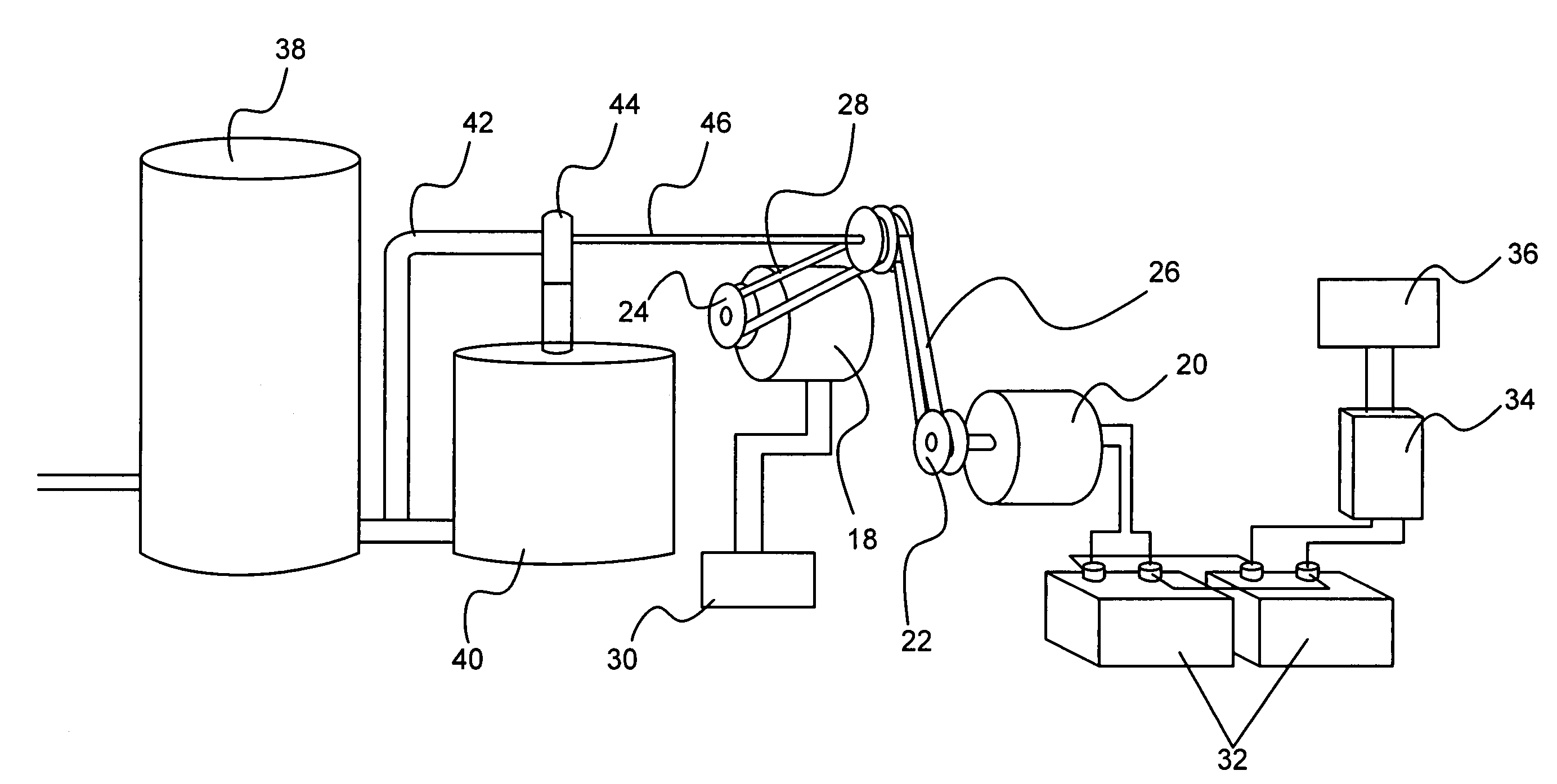
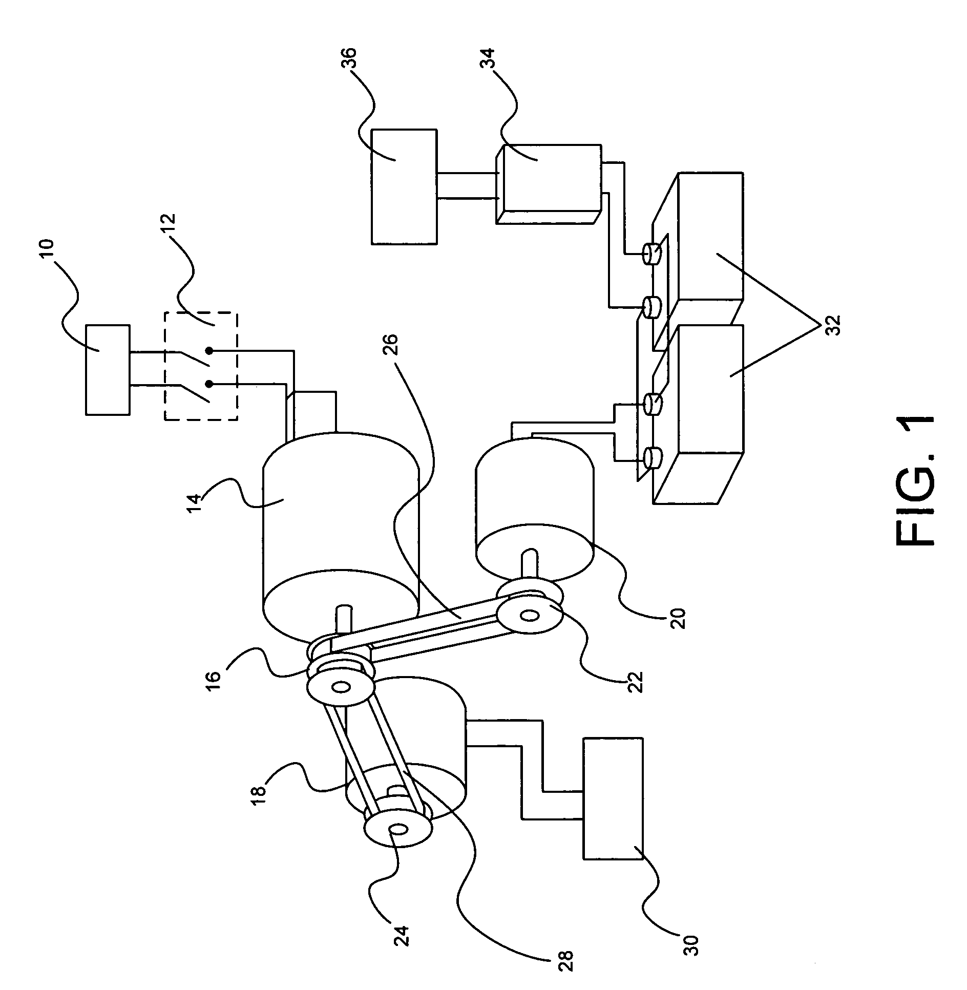
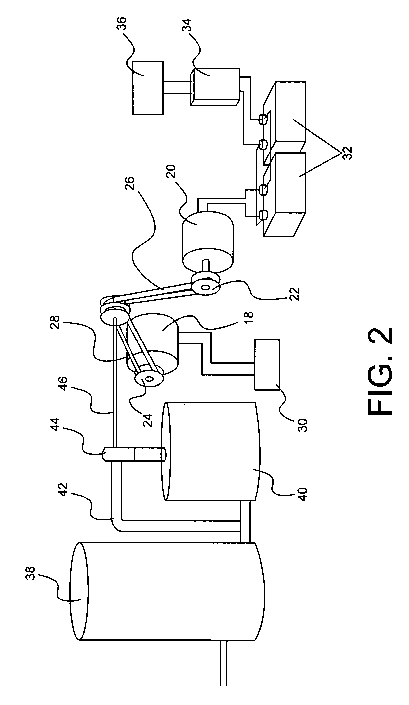
"The present invention is a power distribution system for retrofitting to a household or building. It includes a means for supplying energy to the system for an indeterminate period of time. The energy is converted into motion by an alternator or electric motor, which is then converted into an electric current by a generator. The electric current is used to power a high-load circuit, such as the household's air conditioner or low-wattage appliances. The system also includes a battery bank that stores the energy for later use by a low-load circuit, such as televisions or computers. The power distribution system can be controlled by a main switch and may be integrated with the HVAC thermostat for activating the energy converting means when air conditioning or heating is needed. The technical effects of the invention include efficient energy conversion and storage, as well as flexible and effective power distribution for various household loads."

Problems solved by technology

When a community loses power, there is often a shortage of gasoline because of inoperability of fuel station pumps and increased demand on limited gasoline supplies.
Also, power from “renewable” sources can be expensive or otherwise impractical to obtain for some households.

Method used


Image

  • Retrofittable power distribution system for a household
  • Retrofittable power distribution system for a household
  • Retrofittable power distribution system for a household

Examples


Embodiment Construction

[0016]The present invention, a power distribution system for retrofitting to a household or other building, is illustrated in FIG. 1. The power distribution system includes a means for supplying energy to the power distribution system for an indeterminate period of time. In the current example, the power distribution system receives electrical power from electrical power source 10. Electrical power source 10 may be the household's primary electrical power source. For example, the household owner may use the main power input to the household's primary electrical load center as an input to the power distribution system.

[0017]The power distribution system further comprises a means for converting the energy supplied to the power distribution system into motion. Various energy converting means capable of converting energy to motion may be employed in the present invention. In the example illustrated in FIG. 1, electric motor 14 is used to convert electrical energy into rotational motion ...


PUM


Abstract

A power distribution system for retrofitting to households and other buildings. The power distribution system includes a means for supplying energy to the power distribution system for an indeterminate period of time. The power distribution system further comprises a means for converting the energy supplied to the power distribution system into motion. A generator is operatively connected to the energy converting means and converts the motion produced by the energy converting means into an electric current. The electric current produced by the generator is used to power a high-load circuit. An alternator is also operatively connected to the energy converting means. The alternator is configured to convert the motion produced by the energy converting means into another electric current. The alternator transmits this electric current to a bank of batteries which stores the charge. An inverter is electrically connected to the bank of batteries and transmits an electric current from the bank of batteries to a low-load circuit.

Description

BACKGROUND OF THE INVENTION[0001]1. Field of the Invention[0002]This invention relates to the field of household power distribution systems. More specifically, this invention comprises a retrofittable power distribution system for delivering power to a household or other building via high-load and low-load power circuits.[0003]2. Description of the Related Art[0004]Various power distribution systems exist for household applications. Most households obtain power from a common electrical power grid as a primary power source. Some of the other power systems serve as a back-up power supply for the household when the household's primary power source is not functional. Most back-up power supply systems are stand-alone systems which operate independently of the household's primary power source. Gas-powered generators are the most common back-up power supply systems. Gas-powered generators are generally activated manually when a household loses power provided by the primary power system.[00...

Claims


Application Information

Patent Timeline
Patent Type & Authority Patents(United States)
IPC IPC(8): F01C13/00F02C6/00F02N11/00H02P9/04
CPCH02J9/062H02M5/32H02M5/38
Inventor BLACKMAN, TRACY
Owner BLACKMAN TRACY
Learn More