Pattern light irradiation device, three dimensional shape measuring device, and method pattern light irradiation

a technology measurement device, which is applied in the direction of measurement device, using optical means, instruments, etc., can solve the problems of increasing the cost of pattern light irradiation device, and considerable large lens size and high cos

Inactive Publication Date: 2008-06-17
ORMON CORP
View PDF17 Cites 34 Cited by
  • Summary
  • Abstract
  • Description
  • Claims
  • Application Information

AI Technical Summary

Benefits of technology

[0049]Furthermore, in accordance with another embodiment, the whole area of the sinusoidal wave pattern can be always projected onto the target object, as opposed to a device in which amplitude (luminance) modulation is performed with time using the modulating signal, when the light is projected onto the physical object. In that manner, when the pattern light irradiation device is used, for example, in a three-dimensional shape measuring device, height information of the whole of the required area can be obtained on the basis of the image taken at a certain moment. That is, when the image of the sinusoidal wave pattern is taken, shutter speed can be increased.
[0065]That is, the minimum luminance value in the sinusoidal wave pattern can be decreased, thereby increasing the amplitude of the sinusoidal wave pattern. This means that the contrast of the sinusoidal wave pattern increases and the SN ratio increases. Therefore, if height information of the physical object is measured using the sinusoidal wave pattern, high accuracy measurement can be made.

Problems solved by technology

Such a lens is considerably large and very expensive, as compared with a lens having approximately 43 mm in image circle for use in normal 35 mm film cameras.
Consequently, the cost of the pattern light irradiation device increases.
This remains a problem even if liquid crystal elements are used to form a sinusoidal contrasting density pattern.
That is, a special light source is required and therefore cost of the pattern light irradiation device increases and reduction in size is difficult.
Meanwhile, for the method in which light, in which amplitude modulation is generated with time by a modulating signal, is scanned on a target object is not suitable for analyzing the imaged image.
Furthermore, in the method using a micro lens array described in JPA 8-313209, when the light source is not of a single wavelength, each lens used in the micro lens array is limited to a single plate (single lens) configuration and therefore focal length changes in response to the wavelength of the light from the light source and the effect of chromatic aberration remains.
Consequently, there arises a problem as in the case of using the diffraction grating.
Further, in the method of using a micro lens array, there is also a problem in it is difficult to change the shape of the irradiation pattern.
Much cost is required for replacement of the entire micro lens array and therefore changing the shape of the irradiation pattern can prove to be difficult.

Method used


Image

  • Pattern light irradiation device, three dimensional shape measuring device, and method pattern light irradiation
  • Pattern light irradiation device, three dimensional shape measuring device, and method pattern light irradiation
  • Pattern light irradiation device, three dimensional shape measuring device, and method pattern light irradiation

Examples


example

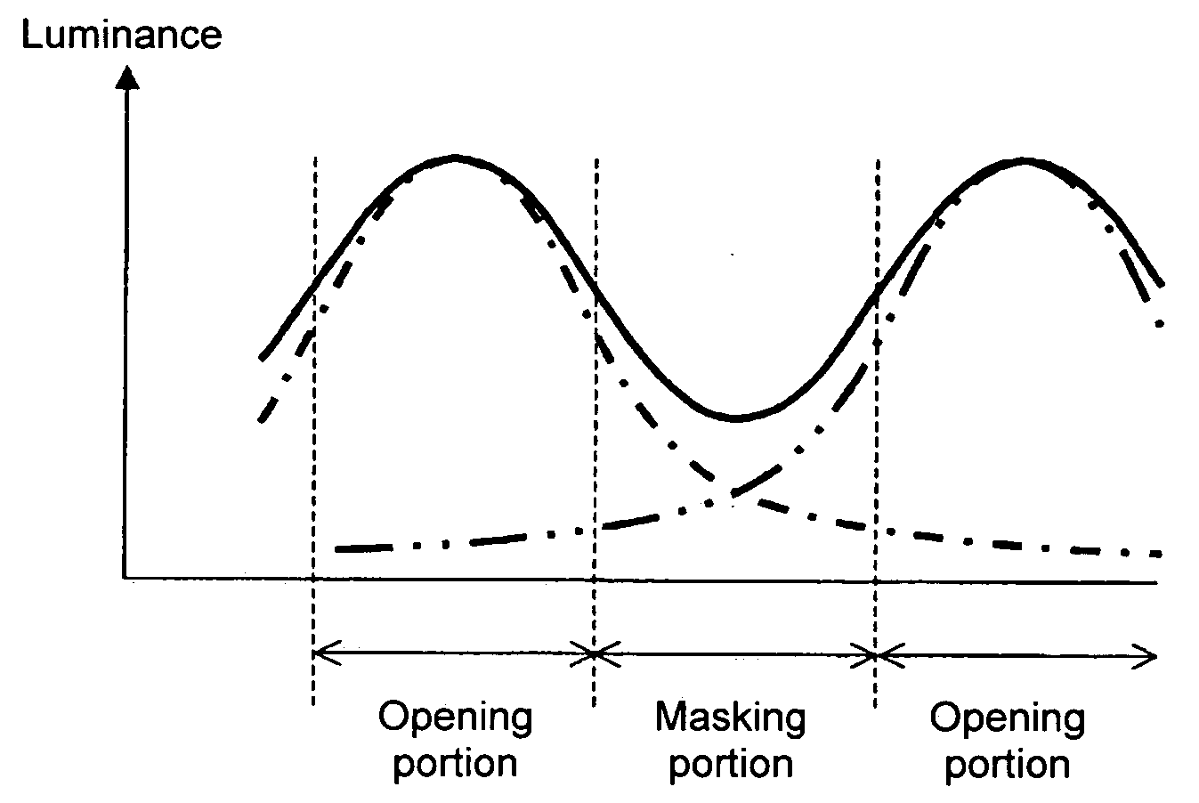
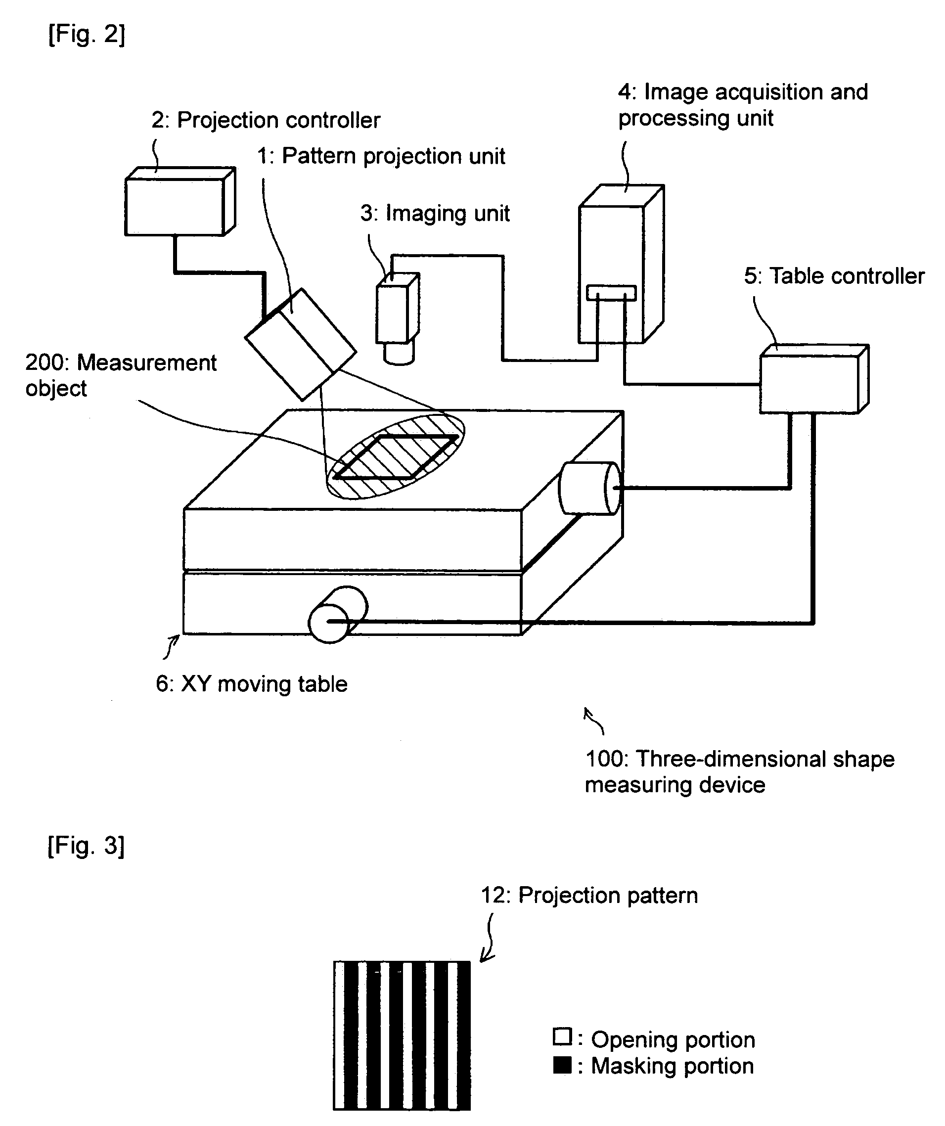
[0096]Next, an experimental example according to the present invention will be described using FIG. 15 to FIG. 17. In the present example, a liquid crystal element arranged in lattice shape was used as a projection pattern 12. The pitch of the opening portions of the projection pattern 12 (that is, a distance from the center of a certain opening portion to the center of the neighboring opening portions) was set to 100 μm. This corresponded to 10LP (Line Pair) / mm which was a value that was able to be easily manufactured without using a particular technique in the configuration of the liquid crystal element. According to this configuration, the size necessary for projecting a sinusoidal wave pattern having 200 pitches within one visual field was as follows:

100(μm)×200(pitch)=20(mm)

Consequently, this size is applicable to lens used in a usual 35 mm film camera or similar devices.

[0097]The width of the opening portion and that of a masking portion was set to 1:1.7. Meanwhile, a condense...


PUM


Abstract

A light irradiation device for irradiating light having a pattern onto a physical object, includes a pattern forming plate provided with a plurality of opening portions; a light irradiation unit for irradiating light towards the pattern forming plate; and a projection lens irradiated by the light irradiation unit, for integrally condensing light passed through an opening of the pattern forming plate and guiding the condensed light to the physical object, wherein the projection lens is arranged such that an image of the pattern forming plate is not focused onto the physical object, but is projected as a sinusoidal wave pattern.

Description

BACKGROUND OF THE RELATED ART[0001]1. Field of the Invention[0002]The present invention relates to a light irradiation device and a method of pattern light irradiation, and further relates to a three-dimensional shape measuring device using the pattern light irradiation device.[0003]2. Description of the Related Art[0004]In a three-dimensional shape measuring device, there is one in which a light pattern is projected to a physical body to be a target object and an irradiation pattern is analyzed using a phase analysis method such as a fringe analysis method, thereby obtaining three-dimensional information (height information) of the object. To describe such a device in more detail, first, an image of a pattern forming plate is projected to a target object by irradiating light toward the target object from a light source via a pattern forming plate. Then, the target object in which the image of the pattern forming plate is projected is imaged to obtain an image. Next, a pattern of th...

Claims


Application Information

Patent Timeline
Patent Type & Authority Patents(United States)
IPC IPC(8): G01B11/24
CPCG01B11/2527
Inventor YOSHINO, MASANAOMURATA, YOSHIROASOKAWA, YOSHINOBU
Owner ORMON CORP
Why Eureka
Try Eureka