
System and method for controlling network traffic flow in a multi-processor network

a multi-processor network and traffic flow technology, applied in data switching networks, frequency-division multiplexes, instruments, etc., can solve problems such as poor network performance, network overflow, and corresponding errors in information being transmitted over the network, and achieve the effect of maximizing network efficiency and being simple to implemen

Active Publication Date: 2008-06-17
HEWLETT-PACKARD ENTERPRISE DEV LP
View PDF6 Cites 9 Cited by
  • Summary
  • Abstract
  • Description
  • Claims
  • Application Information

AI Technical Summary

Benefits of technology

[0010]An advantage of the present invention is that it provides the ability to maximize network efficiency by controlling the amount of traffic that is present on the network.
[0011]Another advantage of the present invention is that it provides the ability to control the transmission rate of data onto a network.
[0012]Yet another advantage of the present invention is that it uses existing network resources.
[0013]Still yet another advantage of the present invention is that it can be used in larger network environments, where one network communicates with a completely different network.
[0014]A feature of the present invention is that it is straightforward to implement.

Problems solved by technology

When more than one computer sends information, or requests control of the communication link, the increased flow of information provided to the network from the transmitting or requesting computers causes the network to become overloaded.
An overloaded network results in poor network performance and corresponding errors in the information that is being transmitted over the network.
Such conventional approaches are often complex and prone to errors.

Method used


Image

  • System and method for controlling network traffic flow in a multi-processor network
  • System and method for controlling network traffic flow in a multi-processor network
  • System and method for controlling network traffic flow in a multi-processor network

Examples


Embodiment Construction

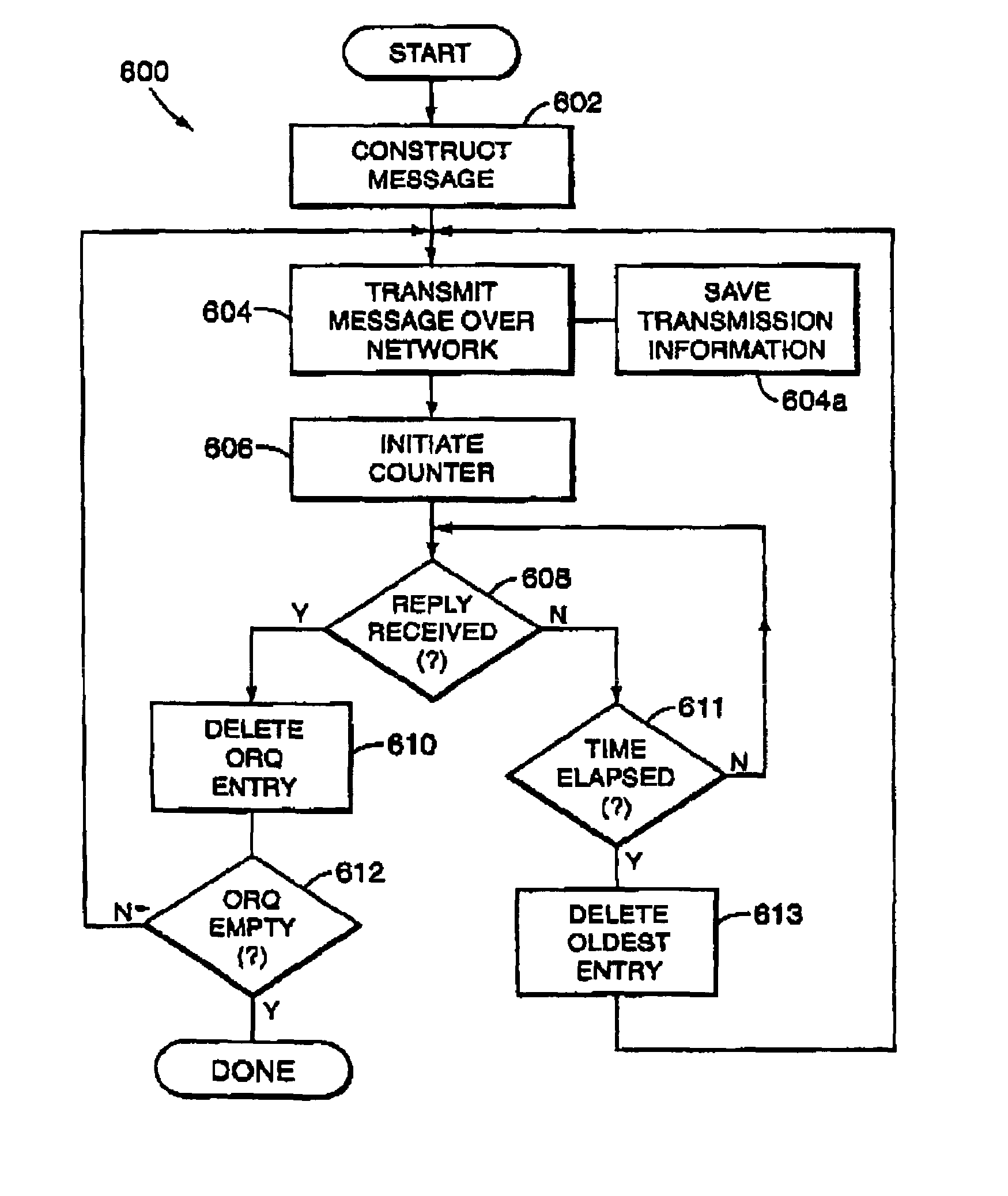
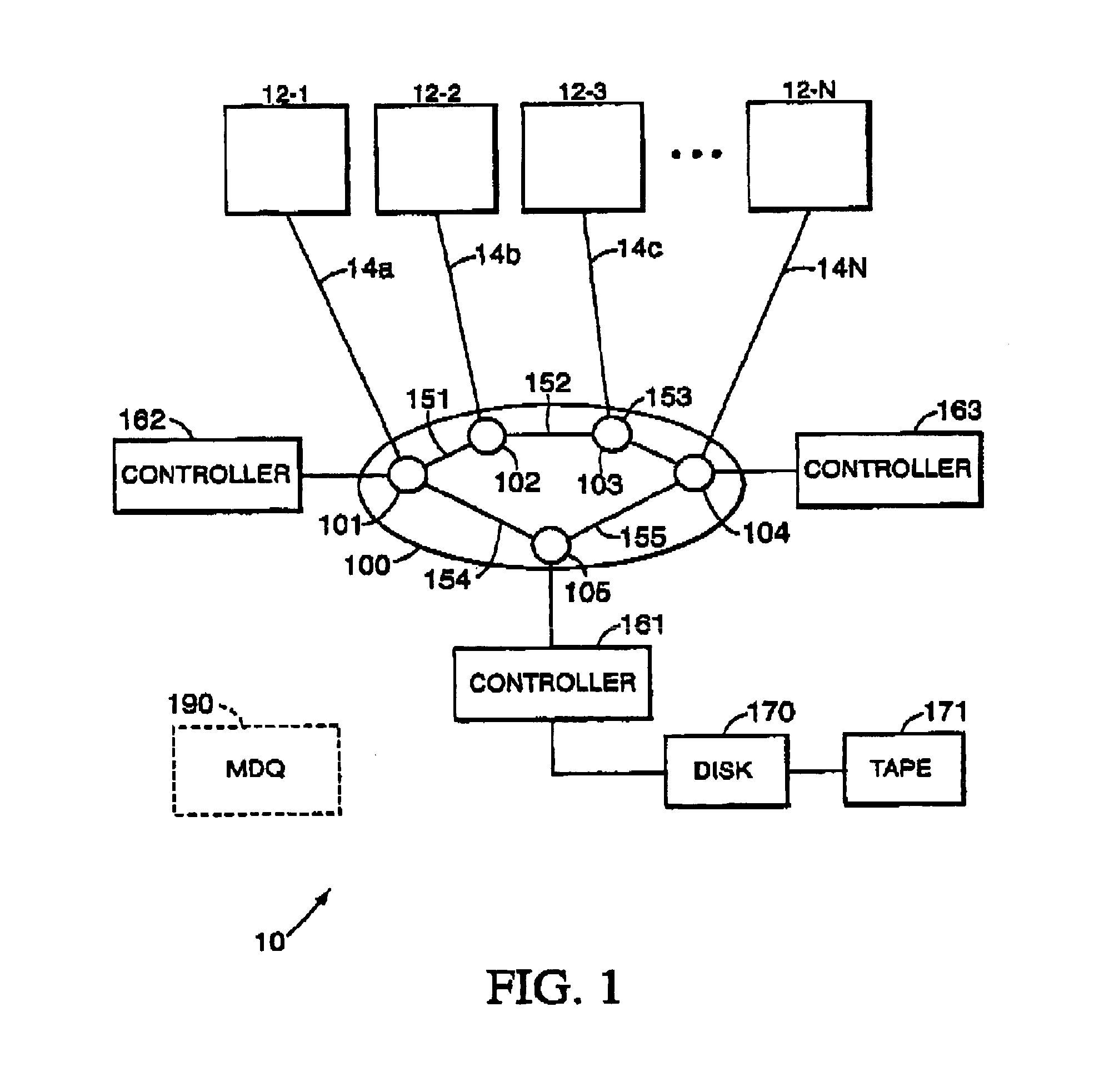
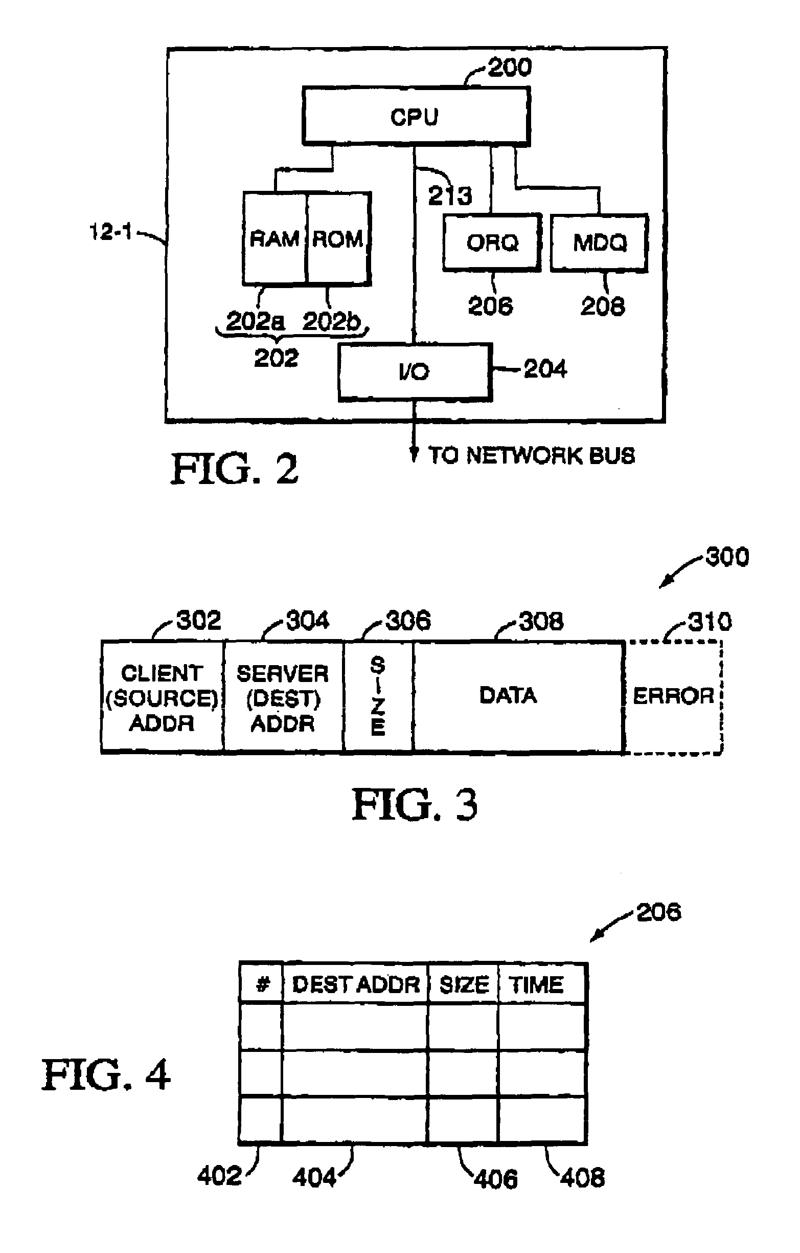
[0022]The present invention will now be described with reference to FIGS. 1-6. FIG. 1 is a schematic representation of a multi-processor network incorporating the traffic flow control protocol of the present invention. Network 10 includes a plurality of nodes, each having a processing device (i.e., personal computer) 12-1, 12-2 . . . 12-N, or other suitable device connected to a corresponding network bus comprised of a series of links 14A-14N. Each of the processing devices 12-1-12-N is substantially similar in structure. Thus, only processing device 12-1 will be described in greater detail below.

[0023]The processing devices 12-1-12-N communicate with one another through a communication network 100. An exemplary network is described in U.S. Pat. No. 5,751,932, also assigned to the assignee of the present invention, which is incorporated herein by reference. The discussion of the exemplary network is for purposes of illustration and example, and is not intended to limit the scope or ...


PUM


Abstract

A system and method for controlling network traffic flow in a multi-processor network is disclosed. The method employs a two-part algorithm to determine when it is appropriate for a client node to transmit data over a network to one or more server nodes. The first part of the algorithm calls for the client node to transmit data over the network after receiving an acknowledgement from one or more of the server nodes to which data transfer is outstanding. The second part of the algorithm provides for the client node transmitting data over the network after a predetermined time interval has elapsed since a data transmission. The time interval is based, in part, on the length of outstanding data packets and a statistical analysis of the number of nodes transmitting or receiving data packets. The transmission of data over the network is accomplished by a hybrid scheme, comprising a combination of PUSH and PULL transmission protocols.

Description

[0001]The present application claims the benefit of U.S. Provisional Application Ser. No. 60 / 227,737, filed Aug. 24, 2000.FIELD OF THE INVENTION[0002]The present invention generally relates to multi-processor networks and, more particularly, to a system and corresponding method for controlling traffic flow within a multi-processor network.BACKGROUND OF THE INVENTION[0003]Multi-processor networks are commonly used in today's office and computing environment. One example of a multi-processor network is a local area network (LAN). In LAN's, several computers, or suitable devices, are interconnected to a common communication link (i.e., a bus) by way of an interface. The computers communicate with one another by sending messages over the communication link. When one computer wants to communicate to a specific computer or broadcast a message to all the computers connected to the network, the sending computer gains access to the communication link and then transmits the message over the l...

Claims


Application Information

Patent Timeline
IPC IPC(8): H04L12/26H04L12/56H04L29/06H04L29/08H04L29/12
CPCH04L29/06H04L47/10H04L47/28H04L67/325H04L29/12018H04L61/10H04L67/62H04L9/40
Inventor NAIK, SACHIN U.JARDINE, ROBERT L.TORII, TATSUHIRO
Owner HEWLETT-PACKARD ENTERPRISE DEV LP
Learn More