Unlock instant, AI-driven research and patent intelligence for your innovation.

Image-processing method and image processor

a processing method and image technology, applied in the field of image processing methods and image processors, can solve the problems of destroying subjective image quality, noise appearing on decoded images, and mosquito noise, and achieve the effect of reducing time and reducing area

Inactive Publication Date: 2008-06-17
SOCIONEXT INC
View PDF8 Cites 0 Cited by
  • Summary
  • Abstract
  • Description
  • Claims
  • Application Information

AI Technical Summary

Benefits of technology

[0054]In view of the above, an object of the present invention is to provide an image processor and image-processing method for inhibiting an area increase in an image processor, processing image data in a reduced time, and coping with a change in image size.

Problems solved by technology

At the same time, the discrete cosine transform brings up a problem of peculiar Gaussian noise called a mosquito noise.
The noise appears on a decoded image, and spoils subjective image quality.
Such a requirement causes a problem of an area increase in an image processor.
Another problem is that the image data are filtered in a lengthy time because each gang of three-pixels-by-three-pixels image data is read out, for each time of the filtering, from the line buffer 502 to repeat the above steps.
This causes a further problem that a change in image size precludes the filtering of the image data.

Method used


Image

  • Image-processing method and image processor
  • Image-processing method and image processor
  • Image-processing method and image processor

Examples


first embodiment

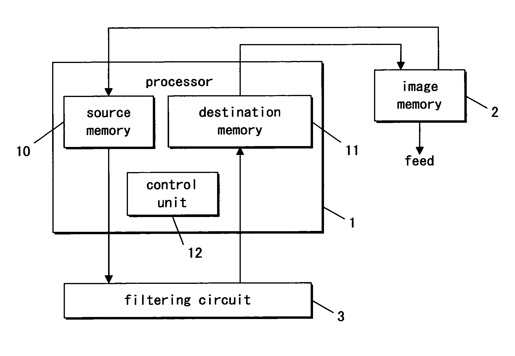
[0122]FIG. 1 is a block diagram illustrating an image processor according to a first embodiment.

[0123]As illustrated in FIG. 1, the image processor includes a processor 1, an image memory 2, and a filtering circuit 3.

[0124]The processor 1 includes a source memory 10, a destination memory 11, and a control unit 12.

[0125]Next, the entire behavior of the image processor is briefly discussed.

[0126]The processor 1 reads out encoded image data from the image memory 2 and writes the same encoded image data into the source memory 10.

[0127]The processor 1 decodes the encoded image data in the source memory 10.

[0128]The processor 1 at first places the decoded image data into the destination memory 11, and then transfers the same image data to the image memory 2 from the destination memory 11.

[0129]The decoded image data transferred to the image memory 2 is filtered.

[0130]In order to filter the decoded image data, 3-lines-by-176-pixels image data are divided into partitions in accordance with ...

second embodiment

[0247]An image processor according to a second embodiment includes a filtering circuit 4 substituted for the filtering circuit 3 of FIG. 1. The filtering circuit 4 is discussed below. The image processor according to the present embodiment is similar in construction to the image processor of FIG. 1 except for the filtering circuit just discussed above.

[0248]FIGS. 8(a), 8(b), and 8(c) are illustrations showing a flow of filtering steps. FIG. 8(a) is an illustration showing a flow of the first filtering. FIG. 8(b) is an illustration showing a flow of the second filtering. FIG. 8(c) is an illustration showing a flow of the third filtering. FIG. 8 illustrates the same reference characters on components similar to those shown in FIG. 1.

[0249]FIG. 9 is a block diagram illustrating the filtering circuit 4. As shown in FIG. 9, the filtering circuit 4 includes a data output control unit 80 other than the same components as those of the filtering circuit 3 of FIG. 4.

[0250]The data output cont...

third embodiment

[0335]An image processor according to a third embodiment includes a filtering circuit substituted for the filtering circuit 3 of FIG. 1. The filtering circuit 5 is discussed below. The image processor according to the present embodiment is similar to those of the image processor of FIG. 1 except for the filtering circuit as just discussed above.

[0336]FIG. 15 is a block diagram illustrating the filtering circuit 5. As shown in FIG. 15, the filtering circuit 5 includes a pixel-retaining buffer unit 50, selectors 52, 53, and a selector controller 51, other than components of the filtering circuit 4 of FIG. 9.

[0337]Filtering is now discussed in brief.

[0338]FIG. 16 is a schematic illustration showing how the image processor according to the present embodiment is operable to filter target image data subject to filtering. FIG. 16 is similar in notation to FIG. 2.

[0339]As illustrated in FIG. 16, three-pixels-by-five-pixels image data 101 obtained by dividing 3-lines-by-176-pixels image data...


PUM


Abstract

Image data is separated from three lines of image data in accordance with a storage capacity of a source memory. The separated image data is transferred to the source memory, Several pieces of image data are read out in sequence from the transferred image data and forwarded to a filtering process. These operations are then repeated to provide a line of filtered image data.

Description

BACKGROUND OF THE INVENTION[0001]1. Field of the Invention[0002]The present invention relates to an image-processing method and image processor for filtering image data to operatively remove encoding-caused noises.[0003]2. Description of the Related Art[0004]Encoded and decoded images over a videophone and a TV conference have heretofore been used to provide a reduced amount of image information in order to achieve efficient image transmission.[0005]A majority of such an image encoding-decoding method in recent years uses discrete cosine transform.[0006]The discrete cosine transform achieves a substantial reduction in image information amount. At the same time, the discrete cosine transform brings up a problem of peculiar Gaussian noise called a mosquito noise. The noise appears on a decoded image, and spoils subjective image quality.[0007]The Gaussian noise as represented by the mosquito noise is removable using a spatial filter. The spatial filter functions to remove high-frequenc...

Claims


Application Information

Patent Timeline
IPC IPC(8): H04N7/18G06T1/20G06T5/20H04N1/40H04N1/409H04N1/41H04N5/21H04N7/12H04N7/24H04N19/00H04N19/426H04N19/625H04N19/80H04N19/86
CPCH04N19/433H04N19/80
Inventor OHASHI, MASAHIRO
Owner SOCIONEXT INC