Process and apparatus for locating coated cooling holes on turbine vanes

a technology of coating cooling holes and turbine vanes, which is applied in vessel construction, instruments, image enhancement, etc., can solve the problems of difficult turbofixing of some vanes, critical locating of cooling holes to remove thermal barrier coatings, and time-consuming turbofixing, so as to reduce process and turnaround time and facilitate use

Inactive Publication Date: 2008-06-17
RTX CORP
View PDF9 Cites 20 Cited by
  • Summary
  • Abstract
  • Description
  • Claims
  • Application Information

AI Technical Summary

Benefits of technology

[0008]Accordingly, it is an object of the present invention to provide improved processes and systems for locating the positions of coated cooling holes on turbine vanes.
[0009]It is another object of the present invention to provide processes and systems as above which is easy to use and reduces process and turnaround time.

Problems solved by technology

If used on turbine vanes, this process will save time and labor in the turbofixing, blending and laser drilling operations as only the necessary sections are turbofixed and blended.
It is difficult to turbofix some vanes due to the geometry of the vanes and in these cases, locating the cooling holes to remove the thermal barrier coating becomes critical.
Since there is no current process available to locate the cooling holes precisely, all the vanes are fully turbofixed in many cases, even those not needing full treatment.
The problems in locating the TBC coated cooling holes are many.
The first and the most challenging part is that the holes are partially covered by the thermal barrier coating, hidden to various extents, by the coating process.
This method is time consuming and not accurate since the holes are only partially visible at best.

Method used


Image

  • Process and apparatus for locating coated cooling holes on turbine vanes
  • Process and apparatus for locating coated cooling holes on turbine vanes
  • Process and apparatus for locating coated cooling holes on turbine vanes

Examples


Embodiment Construction

)

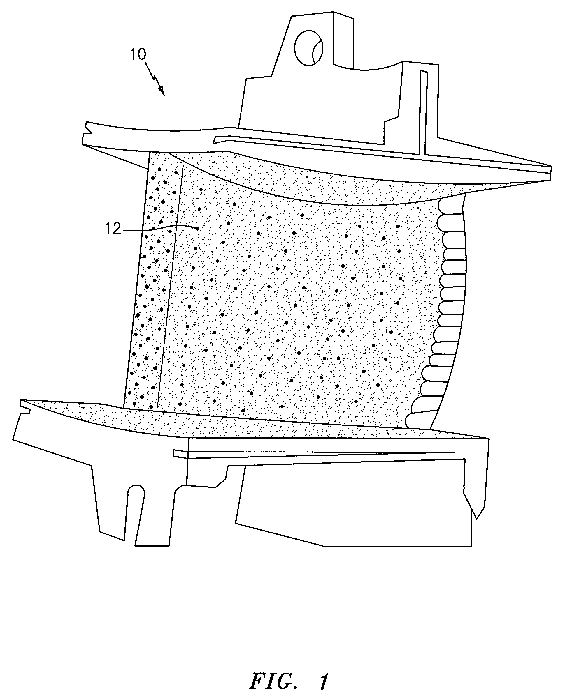
[0026]Referring now to the drawings, FIG. 1 illustrates a turbine vane 10 having a plurality of cooling holes 12. As previously discussed, the cooling holes 12 are typically hidden from view by a thermal barrier coating (not shown) placed on the vane. The problem which the techniques of the present invention is intended to solve is the location of the cooling holes which are partially or wholly hidden by the thermal barrier coating.

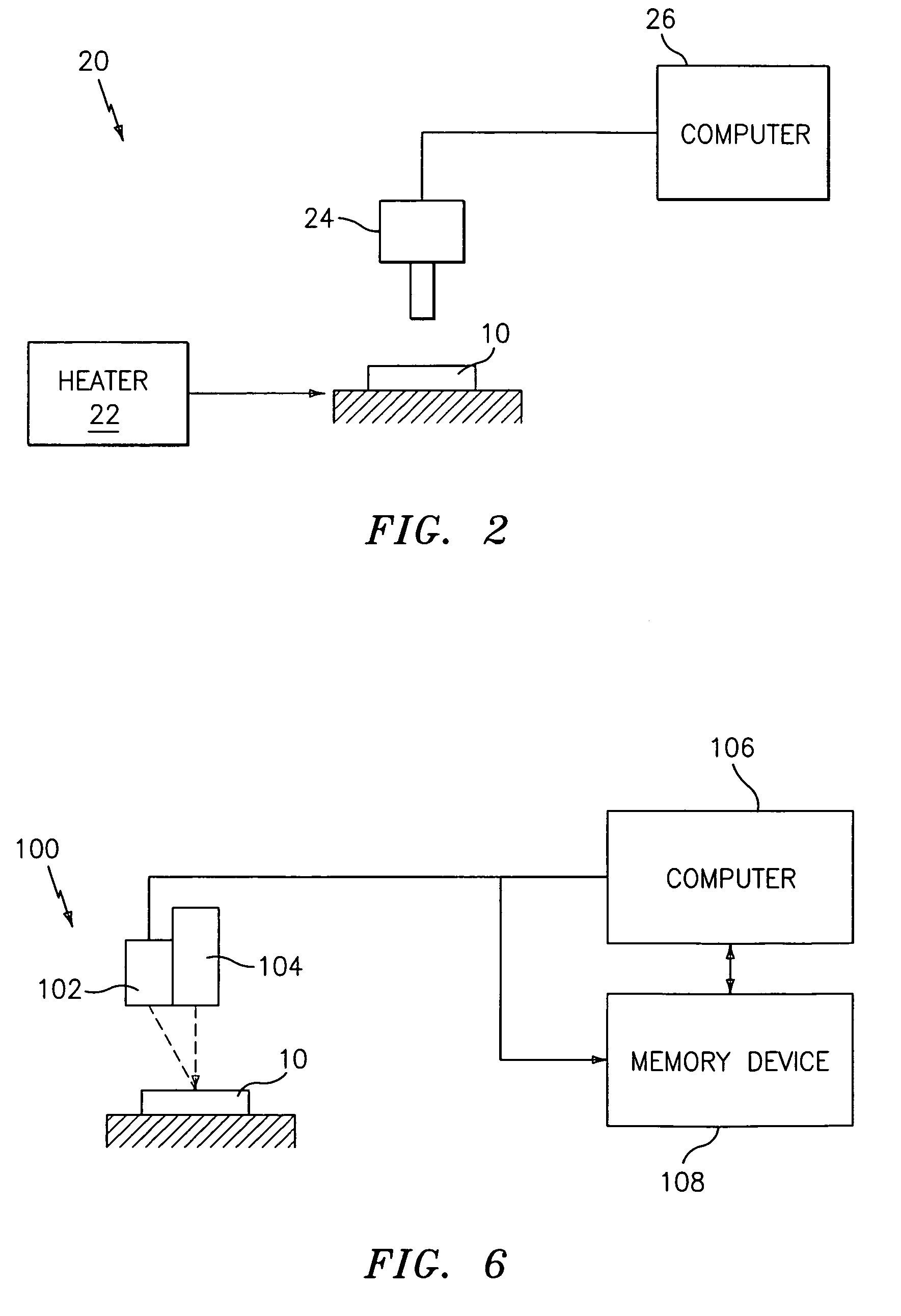
[0027]Referring now to FIG. 2, in a first embodiment of the present invention, a thermal imaging system 20 is utilized to carry out a process for locating the coated cooling holes 12 on a part 10 such as a turbine vane. The system 20 includes a heater 22 for heating the part, preferably substantially uniformly, and an infra red camera 24 for capturing the infra red rays emitted by the part 10. The heater 22 may comprise any suitable heating means known in the art for heating the part 10 to be examined. For example, the heater 22 may comprise a radiant he...


PUM

PropertyMeasurementUnit
diameteraaaaaaaaaa
hole diameteraaaaaaaaaa
depthaaaaaaaaaa

Abstract

The present invention relates to processes and systems for locating coated cooling holes on parts such as turbine vanes. In a first embodiment of the present invention, a thermal imaging technique is utilized to obtain the locations of the cooling holes on a turbine vane. In a second embodiment of the present invention, a laser scanning technique is utilized to obtain the locations of the cooling holes on a turbine vane.

Description

CROSS-REFERENCE TO RELATED APPLICATION(S)[0001]This application is a divisional application of U.S. patent application Ser. No. 09 / 738,966, filed Dec. 15, 2000 now U.S. Pat. No. 6,909,800, entitled PROCESS AND APPARATUS FOR LOCATING COATED COOLING HOLES ON TURBINE VANES, By Janakiraman Vaidyanathan.BACKGROUND OF THE INVENTION[0002]The present invention relates to a process and system for quickly locating coated cooling holes in a part, such as a turbine vane, even though such holes are only partially visible. In a first embodiment of the present invention, the process and the system for locating the coated cooling holes uses thermal imaging techniques to determine the position of the cooling holes. In a second embodiment of the present invention, the process and the system for locating the coated cooling holes uses laser scanning techniques to determine the position and orientation of the cooling holes.[0003]Currently, the repair process for turbine vanes involves cleaning the vanes...

Claims


Application Information

Patent Timeline
Patent Type & Authority Patents(United States)
IPC IPC(8): G06K9/00F01D5/00F01D5/28G06T7/00G06T7/60
CPCB23P6/002F01D5/005F01D5/288G06T7/0004G06T7/0042G06T7/60B23P2700/06G06T2207/30136G06T2207/30164G06T7/73
Inventor VAIDYANATHAN, JANAKIRAMAN
Owner RTX CORP
Why Eureka
Try Eureka