Condition management system and a method of operation thereof

a condition management and condition technology, applied in the field of processing machines, can solve problems such as inability to accommodate all interrupts, inability to develop new interrupt register structures, and inability to meet the needs of simple alarm registers and interrupt mask register structures, so as to reduce the development and maintenance effort of device drivers, and simplify the interface

Inactive Publication Date: 2008-06-17
AVAGO TECH WIRELESS IP SINGAPORE PTE
View PDF16 Cites 22 Cited by
  • Summary
  • Abstract
  • Description
  • Claims
  • Application Information

AI Technical Summary

Benefits of technology

[0010]The present invention introduces the broad concept of abstracting a hierarchical register consolidation structure. This advantageously allows for a simplified interface for traversing and controlling information in the hierarchical register consolidation structure, and for reducing development and maintenance effort for device drivers and application software. The condition management system may also be employed in device interrupt validation and control.

Problems solved by technology

However, if the cause of the interrupt is not determined and passed off to the application software within a certain period of time, the event that caused of the interrupt may be lost or the microprocessor might incur unacceptable delays in processing.
However, a simple alarm register and an interrupt mask register structure could not accommodate all of the interrupts needed.
These new interrupt register structures, however, are not without problems.
Once such problem is the ability of the interrupt software to traverse through the interrupt register structure to determine what caused the interrupt.
This would cause the source code to become huge and unmanageable.
Also, with the increased code size, the source code can become error prone and validation of both the hardware and software becomes an issue.
In addition, as the number of hardware interrupts increases, the ability of the software to detect and handle the increased number of interrupts becomes more difficult.

Method used


Image

  • Condition management system and a method of operation thereof
  • Condition management system and a method of operation thereof
  • Condition management system and a method of operation thereof

Examples


Embodiment Construction

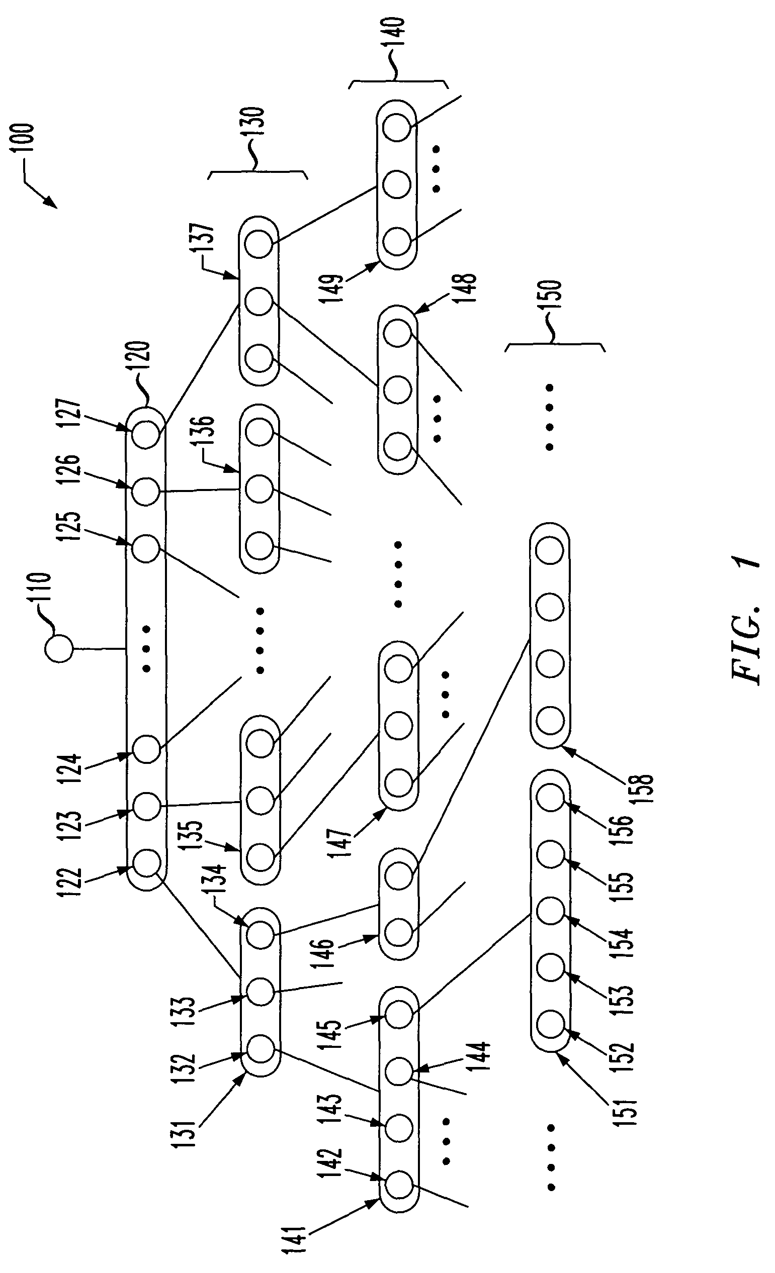
[0025]Referring initially to FIG. 1, illustrated is a diagram of an example of a hierarchical register consolidation structure, generally designated 100, of a processor that may be employed by the present invention. The hierarchical register consolidation structure 100 has a structure similar to a tree structure having branches and leaves. The lowest level of registers (leaves) in the hierarchical register consolidation structure 100 is source level interrupts 150. Typically, the source level interrupts 150 handle all of the alarms or events associated with the physical circuitry of or connected to the processor. The source level interrupts 150 include a plurality of alarm registers 151, 158. The alarm registers 151, 158 are typically of a “write-1-clear” type of register having bits 152-156 for each alarm (or event) associated with that particular alarm register. A “write-1-clear” type of register latches each of the alarm bits, such as alarm bits 152-156, until cleared. Also, one ...


PUM


Abstract

For use with a processor employing a hierarchical register consolidation structure (HRCS), a condition management system and method of operation thereof. In one embodiment, the system includes a condition management structure (CMS) that abstracts groups of status indicators associated with the HRCS into a tree of hierarchical container objects and element objects. Each of the container objects is associated with at least one of the element objects and linked to a single parent object, and each of the element objects configured to represent at least one of the status indicators and linked to a single child object. The system further includes an abstraction retrieval subsystem that employs the CMS to traverse the HRCS to determine a condition of at least one of the status indicators, and an abstraction management subsystem that employs the CMS to control a propagation of selected ones of the status indicators through the HRCS.

Description

TECHNICAL FIELD OF THE INVENTION[0001]The present invention is directed, in general, to processors and, more specifically, to a condition management system for use with processors and a method of operation of a condition management system.LIMITED COPYRIGHT WAIVER[0002]A portion of the disclosure of this patent document contains material to which the claim of copyright protection is made. The copyright owner has no objection to the facsimile reproduction by any person of the patent document or the patent disclosure, as it appears in the U.S. Patent and Trademark Office file or records, but reserves all other rights whatsoever.BACKGROUND OF THE INVENTION[0003]Microprocessors are designed to handle events, such as communication line status and errors, through the use of interrupts. Typically, when a microprocessor receives an event, hardware in the microprocessor sets a bit in an alarm register associated with that particular event. For each bit in the alarm register there is also a co...

Claims


Application Information

Patent Timeline
Patent Type & Authority Patents(United States)
IPC IPC(8): G06F9/44G06F13/24G06F9/48G06F15/00
CPCG06F9/4812
Inventor ECKHART, JASONHOLMES, MICHAEL A.LI, CHANGWILLIAMS, GERALD S.
Owner AVAGO TECH WIRELESS IP SINGAPORE PTE
Why Eureka
Try Eureka